


Chapter 2: Installation
2-21
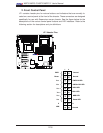
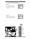
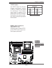
JPI2C1
JPW1
SP1
JPW2
JPW3
JF1
JD1
J5
T-SGPIO2
T-SGPIO1
JPS1
JI2C1
JI2C2
JWD
JPB
JPG1
LE1
JL1
JOH1
FAN7
SLOT1 PCI-E X4
SLOT3 PCI-E 2.0 X4
SLOT7 PCI-E 2.0 X8
LAN1
LAN2
VGA
SLOT6 PCI-E 2.0 X8
SLOT5 PCI-E 2.0 X8
P2-DIMM3A
P2-DIMM3B
P2-DIMM2A
P2-DIMM2B
P2-DIMM1A
P2-DIMM1B
P1-DIMM1B
P1-DIMM1A
P1-DIMM2B
P1-DIMM2A
P1-DIMM3B
SAS4~7
SAS0~3
CPU2 Fan
FAN6
FAN5
FAN2
FAN8/
FAN4
FAN1
P1-DIMM3A
KB/MOUSE
COM1
COM2
I-SATA0
I-SATA2
I-SATA3
I-SATA5
FLOPPY
JWOL
USB6/7
USB4/5
USB3
USB2
FAN3
CPU1
CPU2
CP
Battery
BMC
CTRL
LAN
CTRL
LAN
CTRL
PHY
BIOS
JBT1
Intel 5520
IOH
Intel ICH10R
South Bridge
SIO
I-SATA4
I-SATA1
USB 0/1
IPMI
LAN
X8DT6/E Series
Rev. 2.01
CPU1 Fan
LSI 2008
SAS CTRL
LED1
JIBTN1
D1
SLOT4 PCI-E 2.0 X8
JPL1
JPL2
JP7
TPM
JWF1
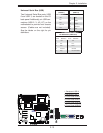
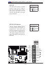
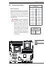
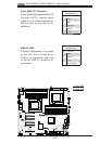
2-6 Connecting Cables
Power Connectors
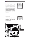
A 24-pin main power supply connector(JPW1)
and two 8-pin CPU PWR connectors (JPW2/
JPW3) are located on the motherboard.
These power connectors meet the SSI EPS
12V specifi cation. See the table on the right
for pin defi nitions.
ATX Power 24-pin Connector
Pin Defi nitions
Pin# Defi nition Pin # Defi nition
13 +3.3V 1 +3.3V
14 -12V 2 +3.3V
15 COM 3 COM
16 PS_ON 4 +5V
17 COM 5 COM
18 COM 6 +5V
19 COM 7 COM
20 Res (NC) 8 PWR_OK
21 +5V 9 5VSB
22 +5V 10 +12V
23 +5V 11 +12V
24 COM 12 +3.3V
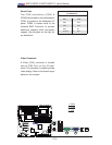
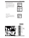
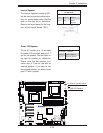
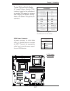
12V 8-pin PWR Connector
Pin Defi nitions
Pins Defi nition
1 through 4 Ground
5 through 8 +12V
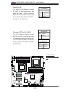
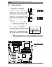
A. 24-pin ATX PWR
(Req'd)
B/C.8-pin Processor PWR
(Req'd)
A
B
C
Warning: To prevent damage to
the power supply or motherboard,
please use a power supply that
contains a 24-pin and two 8-pin
power connectors. Be sure to
connect these connectors to the
24-pin (JPW1) and the two 8-pin
(JPW2,JPW3) power connectors
on the motherboard. Failure in do-
ing so will void the manufacturer
warranty on your power supply and
motherboard.
(Required)
(Required)