


2-16
X8DT6/X8DT6-F/X8DTE/X8DTE-F User's Manual
X8DT6/E Series Rev. 2.01
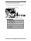
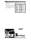
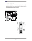
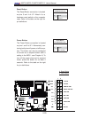
2. Front Control Panel
JF1 contains header pins for various buttons and indicators that are normally lo-
cated on a control panel at the front of the chassis. These connectors are designed
specifi cally for use with Supermicro server chassis. See the fi gure below for the
descriptions of the various control panel buttons and LED indicators. Refer to the
following section for descriptions and pin defi nitions.
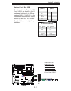
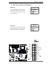
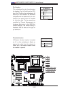
JF1 Header Pins
OH/Fan Fail LED
1
NIC1 LED
2
HDD LED
Power LED
Reset
PWR
Vcc
Vcc
Vcc
Vcc
Ground
Ground
19
20
Vcc
X
Ground
NMI
X
Vcc
PWR Fail LED
NIC2 LED