


2-32
X8DT6/X8DT6-F/X8DTE/X8DTE-F User's Manual
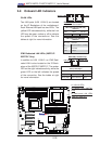
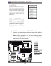
JPI2C1
JPW1
SP1
JPW2
JPW3
JF1
JD1
J5
T-SGPIO2
T-SGPIO1
JPS1
JI2C1
JI2C2
JWD
JPB
JPG1
LE1
JL1
JOH1
FAN7
SLOT1 PCI-E X4
SLOT3 PCI-E 2.0 X4
SLOT7 PCI-E 2.0 X8
LAN1
LAN2
VGA
SLOT6 PCI-E 2.0 X8
SLOT5 PCI-E 2.0 X8
P2-DIMM3A
P2-DIMM3B
P2-DIMM2A
P2-DIMM2B
P2-DIMM1A
P2-DIMM1B
P1-DIMM1B
P1-DIMM1A
P1-DIMM2B
P1-DIMM2A
P1-DIMM3B
SAS4~7
SAS0~3
CPU2 Fan
FAN6
FAN5
FAN2
FAN8/
FAN4
FAN1
P1-DIMM3A
KB/MOUSE
COM1
COM2
I-SATA0
I-SATA2
I-SATA3
I-SATA5
FLOPPY
JWOL
USB6/7
USB4/5
USB3
USB2
FAN3
CPU1
CPU2
CP
Battery
BMC
CTRL
LAN
CTRL
LAN
CTRL
PHY
BIOS
JBT1
Intel 5520
IOH
Intel ICH10R
South Bridge
SIO
I-SATA4
I-SATA1
USB 0/1
IPMI
LAN
X8DT6/E Series
Rev. 2.01
CPU1 Fan
LSI 2008
SAS CTRL
LED1
JIBTN1
D1
SLOT4 PCI-E 2.0 X8
JPL1
JPL2
JP7
TPM
JWF1
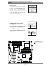
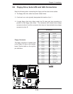
2-8 Onboard LED Indicators
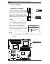
A
B
A. LAN1/2 LEDs
B. LAN3/4 LEDs (X8DT6/i-
LN4)
B. Dedicated LAN LEDs
(X8DT6-F/X8DTE-F)
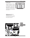
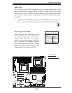
GLAN LEDs
Two LAN ports (LAN 1/LAN 2) are located
on the IO Backplane of the motherboard.
Each Ethernet LAN port has two LEDs. The
yellow LED indicates activity, while the Link
LED may be green, amber or off to indicate
the speed of the connections. See the
tables at right for more information.
LAN 1/LAN 2 Link LED (Right)
LED State
LED Color Defi nition
Off No Connection or 10 Mbps
Green 100 Mbps
Amber 1 Gbps
LAN 1/LAN 2 Activity LED (Left)
LED State
Color Status Defi nition
Yellow Flashing Active
Rear View (when facing the
rear side of the chassis)
Activity LED
Link LED
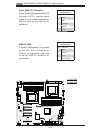
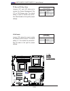
IPMI Dedicated LAN LEDs (X8DT6-F/
X8DTE-F Only)
In addition to LAN 1/LAN 2, an IPMI Dedi-
cated LAN is also located on the IO Back-
plane of the X8DT6-F/X8DTE-F. The amber
LED on the right indicates activity, while the
green LED on the left indicates the speed
of the connection. See the tables at right
for more information.
Link LED
Activity LED
IPMI LAN (F models only)
IPMI LAN Link LED (Left) &
Activity LED (Right)
Color Status Defi nition
Link (Left) Green: Solid 100 Mbps
Activity (Right) Amber: Blinking Active
C