


2-2
X8DT6/X8DT6-F/X8DTE/X8DTE-F User's Manual
X8DT6/E Series Rev. 2.01
Tools Needed
1. Phillips Screwdriver
2. Pan head #6 screws
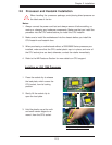
Installation Instructions
Install the IO shield into the chassis. 1.
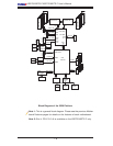
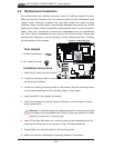
Locate the mounting holes on the motherboard. Refer to the layout above for 2.
mounting hole locations.
Locate the matching mounting holes on the chassis. Align the mounting holes 3.
on the motherboard against the mounting holes on the chassis.
Install standoffs in the chassis as needed.4.
Install the motherboard into the chassis carefully to avoid damage to mother-5.
board components.
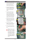
Warning: To avoid damaging the motherboard and its components, please
do not apply any force greater than 8 lb/sq.in (8 lbs. per square inch) when
installing a screw into a mounting hole.
Insert a Pan head #6 screw into a mounting hole on the motherboard and its 6.
matching mounting hole on the chassis, using a Phillips screwdriver.
Repeat Step 4 to insert #6 screws to all mounting holes.7.
Make sure that the motherboard is securely placed on the chassis.8.
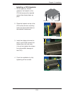
2-2 Motherboard Installation
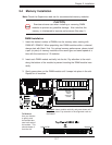
All motherboards have standard mounting holes to fi t different types of chassis.
Make sure that the locations of all the mounting holes for both motherboard and
chassis match. Although a chassis may have both plastic and metal mounting
fasteners, metal ones are highly recommended because they ground the mother-
board to the chassis. Make sure that the metal standoffs click in or are screwed in
tightly. Then use a screwdriver to secure the motherboard onto the motherboard
tray. Note: Some components are very close to the mounting holes. Please take
precautionary measures to prevent damage to these components when installing
the motherboard to the chassis.
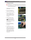
Locations of Mounting Holes