


2-18
X8DT6/X8DT6-F/X8DTE/X8DTE-F User's Manual
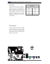
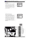
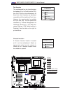
OH/Fan Fail LED
1
NIC1 LED
2
HDD LED
Power LED
Reset
PWR
Vcc
Vcc
Vcc
Vcc
Ground
Ground
19
20
Vcc
X
Ground
NMI
X
Vcc
PWR Fail LED
NIC2 LED
X8DT6/E Series Rev. 2.01
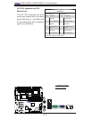
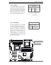
NIC1/NIC2 LED Indicators
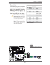
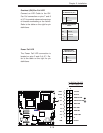
The NIC (Network Interface Control-
ler) LED connection for GLAN port 1 is
located on pins 11 and 12 of JF1, and
the LED connection for GLAN Port 2
is on Pins 9 and 10. Attach the NIC
LED cables to display network activity.
Refer to the table on the right for pin
defi nitions.
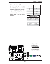
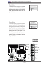
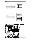
HDD LED
The HDD LED connection is located
on pins 13 and 14 of JF1. Attach a
hard drive LED cable here to display
disk activities (generated from the
ICH10R). See the table on the right
for pin defi nitions.
HDD LED
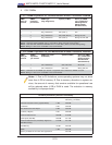
Pin Defi nitions (JF1)
Pin# Defi nition
13 +5V
14 HD Active
GLAN1/2 LED
Pin Defi nitions (JF1)
Pin# Defi nition
9/11 Vcc
10/12 Ground
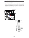
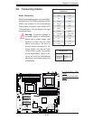
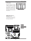
A
B
C
A. HDD LED
B. NIC1 LED
C. NIC2 LED