


2-22
X8DT6/X8DT6-F/X8DTE/X8DTE-F User's Manual
JPI2C1
JPW1
SP1
JPW2
JPW3
JF1
JD1
J5
T-SGPIO2
T-SGPIO1
JPS1
JI2C1
JI2C2
JWD
JPB
JPG1
LE1
JL1
JOH1
FAN7
SLOT1 PCI-E X4
SLOT3 PCI-E 2.0 X4
SLOT7 PCI-E 2.0 X8
LAN1
LAN2
VGA
SLOT6 PCI-E 2.0 X8
SLOT5 PCI-E 2.0 X8
P2-DIMM3A
P2-DIMM3B
P2-DIMM2A
P2-DIMM2B
P2-DIMM1A
P2-DIMM1B
P1-DIMM1B
P1-DIMM1A
P1-DIMM2B
P1-DIMM2A
P1-DIMM3B
SAS4~7
SAS0~3
CPU2 Fan
FAN6
FAN5
FAN2
FAN8/
FAN4
FAN1
P1-DIMM3A
KB/MOUSE
COM1
COM2
I-SATA0
I-SATA2
I-SATA3
I-SATA5
FLOPPY
JWOL
USB6/7
USB4/5
USB3
USB2
FAN3
CPU1
CPU2
CP
Battery
BMC
CTRL
LAN
CTRL
LAN
CTRL
PHY
BIOS
JBT1
Intel 5520
IOH
Intel ICH10R
South Bridge
SIO
I-SATA4
I-SATA1
USB 0/1
IPMI
LAN
X8DT6/E Series
Rev. 2.01
CPU1 Fan
LSI 2008
SAS CTRL
LED1
JIBTN1
D1
SLOT4 PCI-E 2.0 X8
JPL1
JPL2
JP7
TPM
JWF1
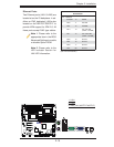
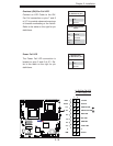
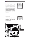
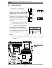
Chassis Intrusion
A Chassis Intrusion header is located
at JL1 on the motherboard. Attach an
appropriate cable from the chassis to
inform you of a chassis intrusion when
the chassis is opened.
Chassis Intrusion
Pin Defi nitions (JL1)
Pin# Defi nition
1 Intrusion Input
2 Ground
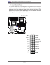
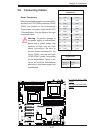
C
A. Fan 1
B. Fan 2
C. Fan 3
D. Fan 4
E. Fan 5
F. Fan 6
G. Fan 7 (CPU1 Fan)
H. Fan 8 (CPU2 Fan)
I. Chassis Intrusion
D
E
F
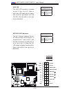
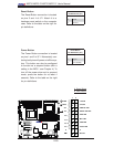
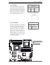
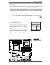
Fan Headers
This motherboard has six chassis/system
fan headers (Fan1 to Fan6) and two CPU
fans (Fan7/Fan8) on the motherboard. All
these 4-pin fans headers are backward
compatible with the traditional 3-pin fans.
However, fan speed control is available
for 4-pin fans only. The fan speeds are
controlled by Thermal Management via
Hardware Monitoring in the BIOS Ad-
vanced Settings. (The Default setting is
Disabled.) See the table on the right for
pin defi nitions.
Fan Header
Pin Defi nitions
Pin# Defi nition
1 Ground
2 +12V
3 Tachometer
4 PWR Modulation
G
I
A
B
H