


2-28
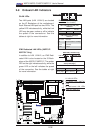
X8DT6/X8DT6-F/X8DTE/X8DTE-F User's Manual
JPI2C1
JPW1
SP1
JPW2
JPW3
JF1
JD1
J5
T-SGPIO2
T-SGPIO1
JPS1
JI2C1
JI2C2
JWD
JPB
JPG1
LE1
JL1
JOH1
FAN7
SLOT1 PCI-E X4
SLOT3 PCI-E 2.0 X4
SLOT7 PCI-E 2.0 X8
LAN1
LAN2
VGA
SLOT6 PCI-E 2.0 X8
SLOT5 PCI-E 2.0 X8
P2-DIMM3A
P2-DIMM3B
P2-DIMM2A
P2-DIMM2B
P2-DIMM1A
P2-DIMM1B
P1-DIMM1B
P1-DIMM1A
P1-DIMM2B
P1-DIMM2A
P1-DIMM3B
SAS4~7
SAS0~3
CPU2 Fan
FAN6
FAN5
FAN2
FAN8/
FAN4
FAN1
P1-DIMM3A
KB/MOUSE
COM1
COM2
I-SATA0
I-SATA2
I-SATA3
I-SATA5
FLOPPY
JWOL
USB6/7
USB4/5
USB3
USB2
FAN3
CPU1
CPU2
CP
Battery
BMC
CTRL
LAN
CTRL
LAN
CTRL
PHY
BIOS
JBT1
Intel 5520
IOH
Intel ICH10R
South Bridge
SIO
I-SATA4
I-SATA1
USB 0/1
IPMI
LAN
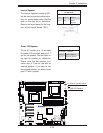
X8DT6/E Series
Rev. 2.01
CPU1 Fan
LSI 2008
SAS CTRL
LED1
JIBTN1
D1
SLOT4 PCI-E 2.0 X8
JPL1
JPL2
JP7
TPM
JWF1
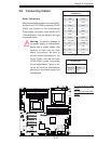
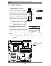
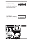
2-7 Jumper Settings
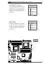
Explanation of Jumpers
To modify the operation of the motherboard,
jumpers can be used to choose between
optional settings. Jumpers create shorts be-
tween two pins to change the function of the
connector. Pin 1 is identifi ed with a square
solder pad on the printed circuit board. See
the motherboard layout pages for jumper
locations.
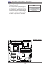
Note: On two pin jumpers, "Closed"
means the jumper is on and "Open"
means the jumper is off the pins.
Connector
Pins
Jumper
Cap
Setting
Pin 1-2 short
3 2 1
3 2 1
A
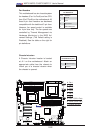
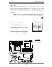
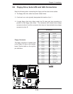
A. SAS Enable (X8DT6/
X8DT6-F
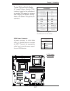
SAS Enable/Disable (X8DT6/X8DT6-F)
Jumper JPS1 allows you to enable or disable
the onboard SAS connections. The default
setting is Pins 1-2 to enable the connec-
tion. See the table on the right for jumper
settings.
SAS Enable
Jumper Settings
Jumper Setting Defi nition
1-2 SAS Enabled (Default)
2-3 SAS Disabled
Note: For information on LSI SAS RAID confi guration, please refer to
the LSI MegaRAID User's Guide @ http://www.supermicro.com/support/
manuals/.