


Chapter 2: Installation
2-23
JPI2C1
JPW1
SP1
JPW2
JPW3
JF1
JD1
J5
T-SGPIO2
T-SGPIO1
JPS1
JI2C1
JI2C2
JWD
JPB
JPG1
LE1
JL1
JOH1
FAN7
SLOT1 PCI-E X4
SLOT3 PCI-E 2.0 X4
SLOT7 PCI-E 2.0 X8
LAN1
LAN2
VGA
SLOT6 PCI-E 2.0 X8
SLOT5 PCI-E 2.0 X8
P2-DIMM3A
P2-DIMM3B
P2-DIMM2A
P2-DIMM2B
P2-DIMM1A
P2-DIMM1B
P1-DIMM1B
P1-DIMM1A
P1-DIMM2B
P1-DIMM2A
P1-DIMM3B
SAS4~7
SAS0~3
CPU2 Fan
FAN6
FAN5
FAN2
FAN8/
FAN4
FAN1
P1-DIMM3A
KB/MOUSE
COM1
COM2
I-SATA0
I-SATA2
I-SATA3
I-SATA5
FLOPPY
JWOL
USB6/7
USB4/5
USB3
USB2
FAN3
CPU1
CPU2
CP
Battery
BMC
CTRL
LAN
CTRL
LAN
CTRL
PHY
BIOS
JBT1
Intel 5520
IOH
Intel ICH10R
South Bridge
SIO
I-SATA4
I-SATA1
USB 0/1
IPMI
LAN
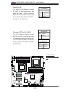
X8DT6/E Series
Rev. 2.01
CPU1 Fan
LSI 2008
SAS CTRL
LED1
JIBTN1
D1
SLOT4 PCI-E 2.0 X8
JPL1
JPL2
JP7
TPM
JWF1
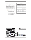
B
A
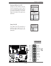
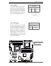
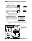
A. Internal Speaker (Buzz-
er)
B. PWR LED/Speaker
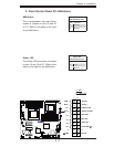
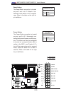
Power LED/Speaker
On the JD1 header, pins 1-3 are used
for power LED indication, and pins 4-7
are for the speaker. See the table on
the right for speaker pin defi nitions.
Please note that the speaker con-
nector pins (4-7) are for use with an
external speaker. If you wish to use
the onboard speaker, you should close
pins 6-7 with a jumper.
Speaker Connector
Pin Setting Defi nition
Pins 6-7 Internal Speaker
Pins 4-7 External Speaker
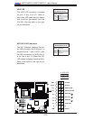
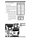
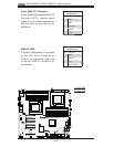
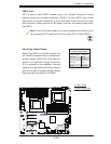
Internal Speaker
The Internal Speaker, located at SP1,
can be used to provide audible indica-
tions for various beep codes. See the
table on the right for pin defi nitions.
Refer to the layout below for the loca-
tions of the Internal Buzzer (SP1).
Internal Buzzer (SP1)
Pin Defi nition
Pin# Defi nitions
Pin 1 Pos. (+) Beep In
Pin 2 Neg. (-) Alarm
Speaker