


Chapter 2: Installation
2-27
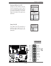
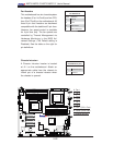
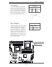
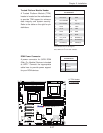
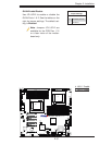
DOM Power Connector
A power connector for SATA DOM
(Disk_On_Module) Devices is located
at JWF1. Connect the appropriate
cable here to provide power support
for your DOM devices.
DOM PWR
Pin Defi nitions
Pin# Defi nition
1 +5V
2 Ground
3 Ground
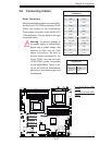
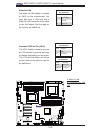
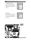
JPI2C1
JPW1
SP1
JPW2
JPW3
JF1
JD1
J5
T-SGPIO2
T-SGPIO1
JPS1
JI2C1
JI2C2
JWD
JPB
JPG1
LE1
JL1
JOH1
FAN7
SLOT1 PCI-E X4
SLOT3 PCI-E 2.0 X4
SLOT7 PCI-E 2.0 X8
LAN1
LAN2
VGA
SLOT6 PCI-E 2.0 X8
SLOT5 PCI-E 2.0 X8
P2-DIMM3A
P2-DIMM3B
P2-DIMM2A
P2-DIMM2B
P2-DIMM1A
P2-DIMM1B
P1-DIMM1B
P1-DIMM1A
P1-DIMM2B
P1-DIMM2A
P1-DIMM3B
SAS4~7
SAS0~3
CPU2 Fan
FAN6
FAN5
FAN2
FAN8/
FAN4
FAN1
P1-DIMM3A
KB/MOUSE
COM1
COM2
I-SATA0
I-SATA2
I-SATA3
I-SATA5
FLOPPY
JWOL
USB6/7
USB4/5
USB3
USB2
FAN3
CPU1
CPU2
CP
Battery
BMC
CTRL
LAN
CTRL
LAN
CTRL
PHY
BIOS
JBT1
Intel 5520
IOH
Intel ICH10R
South Bridge
SIO
I-SATA4
I-SATA1
USB 0/1
IPMI
LAN
X8DT6/E Series
Rev. 2.01
CPU1 Fan
LSI 2008
SAS CTRL
LED1
JIBTN1
D1
SLOT4 PCI-E 2.0 X8
JPL1
JPL2
JP7
TPM
JWF1
A
A. TPM Header
B. DOM Power
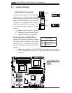
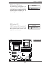
Trusted Platform Module Header
A Trusted Platform Module (TPM)
header is located on the motherboard
to provide TPM support to enhance
data integrity and system security.
Refer to the table on the right for pin
defi nitions.
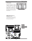
Trusted Platform Module (TPM) Header
Pin Defi nitions
Pin# Defi nition Pin # Defi nition
1 LPC Clock 2 GND
3 LPC FRAME# 4 Key
5 LPC Reset# 6 +5V (X)
7 LAD3 8 LAD2
9 +3.3V 10 LAD1
11 LAD0 12 GND
13 SCL 14 SDAT
15 +3V_DUAL 16 SERIRQ (X)
17 GND 18 CLKRUN(X)
19 LPCPD# (X) 20 LDRQ#(X)
Notes:
(X)=TPM does not use the signals.
SCL, SDAT are I
2
C bus clock and data.
B