


1-6
X9DRD-iF/LF Motherboard User’s Manual
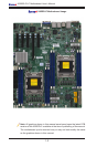
Warning: To avoid damaging your motherboard and components, please use a power
supply that supports a 24-pin, two 4-pin and two 8-pin power connectors. Be sure to
connect the 24-pin and the 8-pin power connectors to your power supply for adequate
power delivery to your system. The 4-pin power connectors are optional; however,
Supermicro recommends that these connectors also be plugged in for optimal power
delivery.
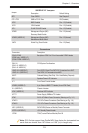
JUIDB UID (Unit Identication) Switch
LAN1/LAN2 G-bit Ethernet Ports 1/2
(IPMI) LAN IPMI_Dedicated LAN
SP1 Onboard Buzzer (Internal Speaker)
(I-)SATA 0~5, SCU0~3
(I-)SATA 0~1 (X9DRD-LF)
Onboard Serial_Link Connections
(SATA Connections 0~5, SCU Connections 0~3)
(CPU1) Slot3, Slot4, Slot5,
(CPU2) Slot7 (X9DRD-iF)
PCI-Express 3.0 x8 Slots (See Note Below)
(CPU2) Slot6 (X9DRD-iF) PCI-Express 3.0 x16 Slot (See Note Below)
PCI-E x16 Slot (X9DRD-LF) PCI-Express 3.0 x16 Slot (from P1PE2) (See note on page 1-5)
(3-)SGPIO 1 (X9DRD-iF) Serial_Link General Purpose I/O Headers for SCU Connec-
tions
(T-)SGPIO 1/2 (X9DRD-iF) Serial ATA (SATA) General Purpose I/O Header
(BP) USB 0/1, 2/3 Back Panel USB 0/1, 2/3
(FP) USB 4/5, USB 8/9
(FP USB4/5 only: X9DRD-LF)
Front Panel Accessible USB Connections (4/5, 8/9)
(FP) USB 6 (X9DRD-iF) Type A USB Embedded Drive Connector
VGA Backpanel VGA Port
LED Indicators
LED Description State Status
LED2 Standby PWR LED Green: On Standby PWR On
LED3 Rear UID LED Blue: On Unit Identied
LEDM1 BMC Heartbeat LED Green: Blinking BMC Normal