


Chapter 2: Installation
2-35
F1
BMC CTRL
LAN CTRL
BIOS
FP CTRL
A1
COM1
1.10Rev.
X9DRD-iF
JBT1
LED2
LEDM1
LED3
JIPMB1
JD1
JUIDB
JPW4
SP1
JSTBY1
JRK1
JPW3
JPW2
JPW1
JBAT1
JL1
JOH1
JI2C2
JI2C1
JWD1
JPG1
JPB1
JPL1
FAN4
FAN5
FAN6
FAN2
FAN1
FAN8
FAN7
T-SGPIO2
T-SGPIO1
SCU0
I-SATA2
I-SATA1
I-SATA0
JF1
JTPM1
G1
H1
E1
C1
D1
USB6
USB4/5
USB8/9
CPU1
CPU1
SLOT7 PCI-E 3.0 X8
CPU2
CPU2
CPU1
B1
SLOT4 PCI-E 3.0 X8
SLOT3 PCI-E 3.0 X8
SLOT5 PCI-E 3.0 X8
SLOT6 PCI-E 3.0 X16
COM2
VGA
LAN2
LAN1
USB2/3
IPMI_LAN
USB0/1
JPME1
LAN
CTRL
BMC
CLK CTRL
JVR1
JVR2
JVRM_I2C2
JVRM_I2C1
PCH
JSD1
I-SATA3
I-SATA4
I-SATA5
SCU1
SCU2
SCU3
S-SGPIO1
FAN3
JPW5
JPI2C1
+
:OH LED
JPME2
CPU1
CPU2
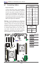
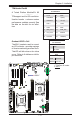
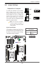
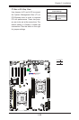
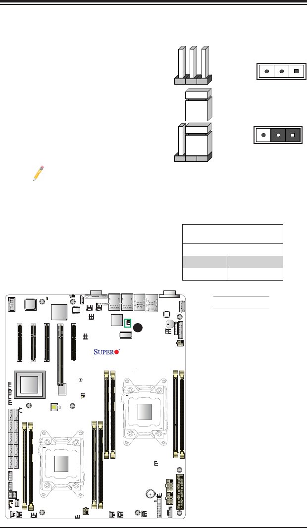
2-8 Jumper Settings
Explanation of Jumpers
To modify the operation of the mother-
board, jumpers can be used to choose
between optional settings. Jumpers create
shorts between two pins to change the
function of the connector. Pin 1 is identied
with a square solder pad on the printed
circuit board. See the motherboard layout
pages for jumper locations.
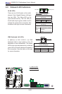
Note: On two-pin jumpers,
"Closed" means the jumper is
on and "Open" means the jumper
is off the pins.
Connector
Pins
Jumper
Cap
Setting
Pin 1-2 short
3 2 1
3 2 1
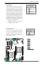
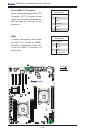
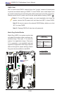
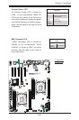
GLAN Enable/Disable
JPL1 enables or disables the GLAN Port1
and GLAN Port2 on the motherboard. See
the table on the right for jumper settings.
The default setting is Enabled.
GLAN Enable
Jumper Settings
Jumper Setting Denition
1-2 Enabled (default)
2-3 Disabled
A
A. GLAN1 Enable
B. GLAN2 Enable