


2-30
X9DRD-iF/LF Motherboard User’s Manual
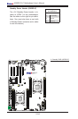
F1
BMC CTRL
LAN CTRL
BIOS
FP CTRL
A1
COM1
1.10Rev.
X9DRD-iF
JBT1
LED2
LEDM1
LED3
JIPMB1
JD1
JUIDB
JPW4
SP1
JSTBY1
JRK1
JPW3
JPW2
JPW1
JBAT1
JL1
JOH1
JI2C2
JI2C1
JWD1
JPG1
JPB1
JPL1
FAN4
FAN5
FAN6
FAN2
FAN1
FAN8
FAN7
T-SGPIO2
T-SGPIO1
SCU0
I-SATA2
I-SATA1
I-SATA0
JF1
JTPM1
G1
H1
E1
C1
D1
USB6
USB4/5
USB8/9
CPU1
CPU1
SLOT7 PCI-E 3.0 X8
CPU2
CPU2
CPU1
B1
SLOT4 PCI-E 3.0 X8
SLOT3 PCI-E 3.0 X8
SLOT5 PCI-E 3.0 X8
SLOT6 PCI-E 3.0 X16
COM2
VGA
LAN2
LAN1
USB2/3
IPMI_LAN
USB0/1
JPME1
LAN
CTRL
BMC
CLK CTRL
JVR1
JVR2
JVRM_I2C2
JVRM_I2C1
PCH
JSD1
I-SATA3
I-SATA4
I-SATA5
SCU1
SCU2
SCU3
S-SGPIO1
FAN3
JPW5
JPI2C1
+
:OH LED
JPME2
CPU1
CPU2
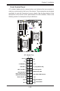
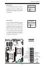
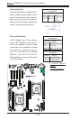
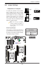
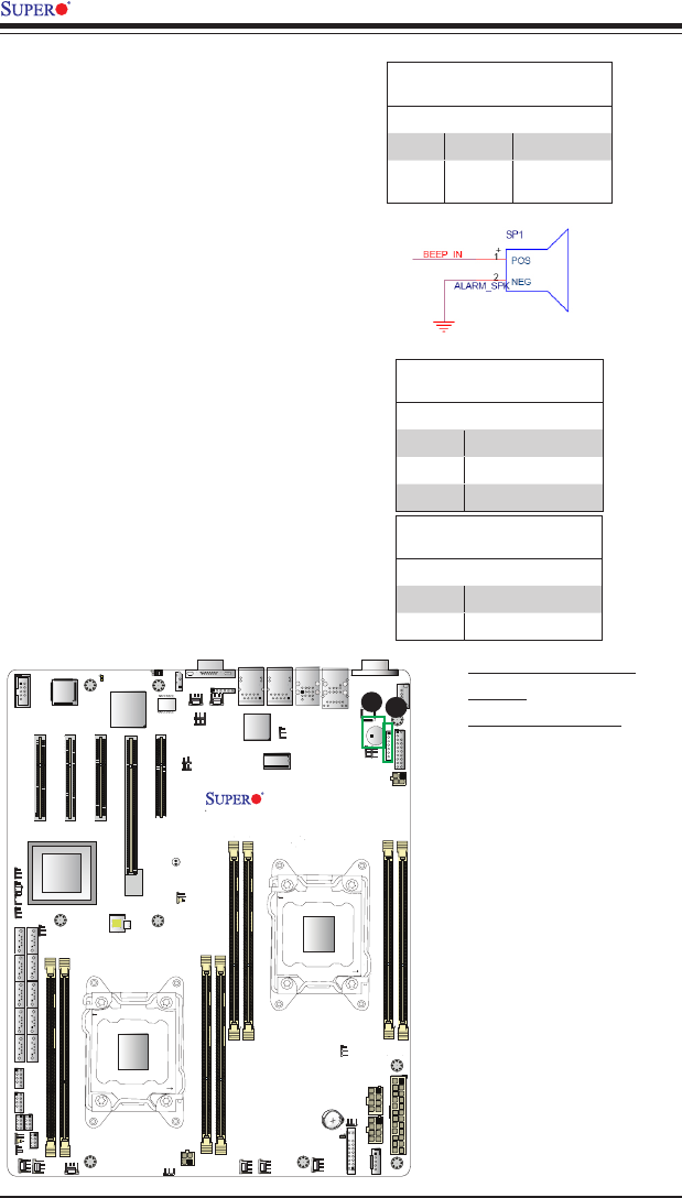
A. Internal Speaker
(Buzzer)
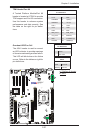
B. PWR LED/Speaker
Power LED/Speaker
On JD1 header, pins 1-3 are used for
power LED indication, and pins 4-7
are for the speaker. See the tables
on the right for pin denitions. Please
note that the speaker connector
pins (4-7) are used with an external
speaker. If you wish to use the on-
board speaker, you should close pins
6-7 with a jumper.
Speaker Connector
Pin Settings
Pin Setting Denition
Pins 4-7 External Speaker
Pins 6-7 Internal Speaker
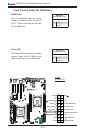
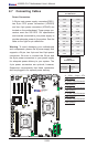
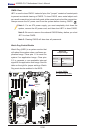
Internal Speaker
The Internal Speaker, located at SP1,
can be used to provide audible indica-
tions for various beep codes. See the
table on the right for pin denitions.
Refer to the layout below for the loca-
tions of the Internal Buzzer (SP1).
Internal Buzzer (SP1)
PinDenition
Pin# Denitions
Pin 1 Pos. (+) Beep In
Pin 2 Neg. (-) Alarm
Speaker
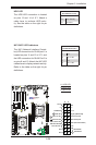
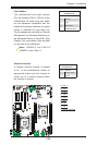
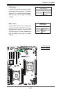
PWR LED Connector
PinDenitions
Pin Setting Denition
Pin 1 Anode (+)
Pin2 Cathode (-)
Pin3 NA
A
B