


Chapter 2: Installation
2-11
F1
BMC CTRL
LAN CTRL
BIOS
FP CTRL
A1
COM1
1.10Rev.
X9DRD-iF
JBT1
LED2
LEDM1
LED3
JIPMB1
JD1
JUIDB
JPW4
SP1
JSTBY1
JRK1
JPW3
JPW2
JPW1
JBAT1
JL1
JOH1
JI2C2
JI2C1
JWD1
JPG1
JPB1
JPL1
FAN4
FAN5
FAN6
FAN2
FAN1
FAN8
FAN7
T-SGPIO2
T-SGPIO1
SCU0
I-SATA2
I-SATA1
I-SATA0
JF1
JTPM1
G1
H1
E1
C1
D1
USB6
USB4/5
USB8/9
CPU1
CPU1
SLOT7 PCI-E 3.0 X8
CPU2
CPU2
CPU1
B1
SLOT4 PCI-E 3.0 X8
SLOT3 PCI-E 3.0 X8
SLOT5 PCI-E 3.0 X8
SLOT6 PCI-E 3.0 X16
COM2
VGA
LAN2
LAN1
USB2/3
IPMI_LAN
USB0/1
JPME1
LAN
CTRL
BMC
CLK CTRL
JVR1
JVR2
JVRM_I2C2
JVRM_I2C1
PCH
JSD1
I-SATA3
I-SATA4
I-SATA5
SCU1
SCU2
SCU3
S-SGPIO1
FAN3
JPW5
JPI2C1
+
:OH LED
JPME2
CPU1
CPU2
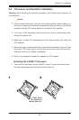
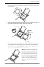
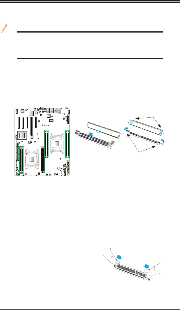
Release Tabs
Notches
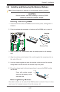
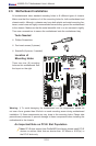
2-4 Installing and Removing the Memory Modules
Note: Check Supermicro's website for recommended memory modules.
CAUTION
Exercise extreme care when installing or removing DIMM
modules to prevent any possible damage.
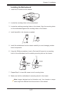
Installing & Removing DIMMs
1. Insert the desired number of DIMMs into the memory slots, starting with P1-
DIMMA1.
2. Push the release tabs outwards on both ends of the DIMM slot to unlock it.
Removing Memory Modules
Press both notches on the ends of the DIMM module to unlock it. Once it is loos-
ened, once it is loosened, remove it from the memory slot.
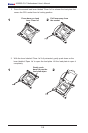
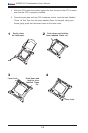
3. Align the key of the DIMM module with the receptive point on the memory
slot.
4. Align the notches on both ends of the module against the receptive points on
the ends of the slot.
5. Use two thumbs together to press the notches on both ends of the module
straight down into the slot until the module snaps into place.
6. Press the release tabs to the locking positions to secure the DIMM module
into the slot.
Press both notches straight
down into the memory slot at
the same time.