


2-40
X9DRD-iF/LF Motherboard User’s Manual
F1
BMC CTRL
LAN CTRL
BIOS
FP CTRL
A1
COM1
1.10Rev.
X9DRD-iF
JBT1
LED2
LEDM1
LED3
JIPMB1
JD1
JUIDB
JPW4
SP1
JSTBY1
JRK1
JPW3
JPW2
JPW1
JBAT1
JL1
JOH1
JI2C2
JI2C1
JWD1
JPG1
JPB1
JPL1
FAN4
FAN5
FAN6
FAN2
FAN1
FAN8
FAN7
T-SGPIO2
T-SGPIO1
SCU0
I-SATA2
I-SATA1
I-SATA0
JF1
JTPM1
G1
H1
E1
C1
D1
USB6
USB4/5
USB8/9
CPU1
CPU1
SLOT7 PCI-E 3.0 X8
CPU2
CPU2
CPU1
B1
SLOT4 PCI-E 3.0 X8
SLOT3 PCI-E 3.0 X8
SLOT5 PCI-E 3.0 X8
SLOT6 PCI-E 3.0 X16
COM2
VGA
LAN2
LAN1
USB2/3
IPMI_LAN
USB0/1
JPME1
LAN
CTRL
BMC
CLK CTRL
JVR1
JVR2
JVRM_I2C2
JVRM_I2C1
PCH
JSD1
I-SATA3
I-SATA4
I-SATA5
SCU1
SCU2
SCU3
S-SGPIO1
FAN3
JPW5
JPI2C1
+
:OH LED
JPME2
CPU1
CPU2
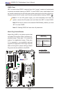
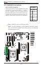
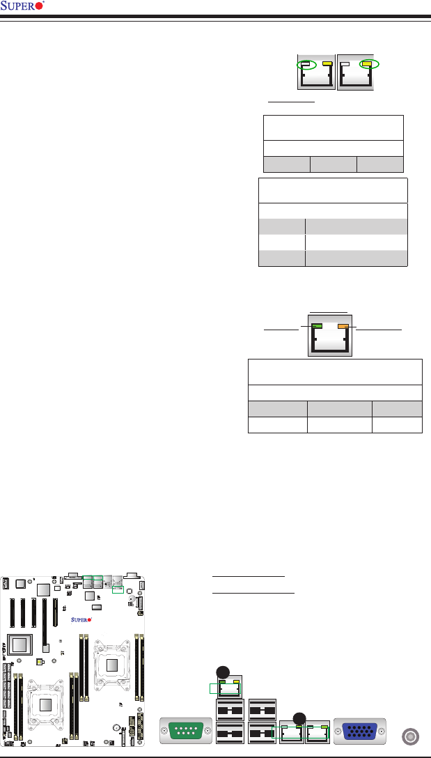
2-9 Onboard LED Indicators
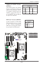
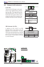
A. LAN1/2 LEDs
B. IPMI LAN LEDs
IPMI Dedicated LAN LEDs
In addition to LAN 1/LAN 2, an IPMI
Dedicated LAN is also located on the I/O
Backplane of the motherboard. The amber
LED on the right indicates activity, while the
green LED on the left indicates the speed of
the connection. See the table on the right
for more information.
LAN 1/LAN 2
IPMI LAN
(X8ST3-F)
Link LED
Activity LED
IPMI LAN
IPMI LAN Link LED (Left) &
Activity LED (Right)
Color/State Denition
Link (Left) Green: Solid 100 Mbps
Activity (Right) Amber: Blinking Active
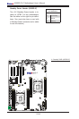
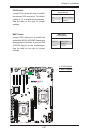
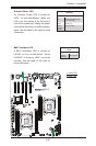
GLAN LEDs
There are two GLAN ports on the moth-
erboard. Each Gigabit Ethernet LAN port
has two LEDs. The Yellow LED on the
right indicates activity. The Link LED on
the left side may be green, amber or off to
indicate the speed of the connection. See
the table on the right for more information.
Activity LED
GLAN Speed/Link Indicator (Left)
LED Settings
LED Color Denition
Off No Connection or 10 Mbps
Green 100 Mbps
Amber 1 Gbps
Link LED
GLAN Activity Indicator (Right)
LED Settings
Color Status Denition
Yellow Flashing Active
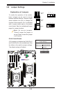
Rear View (when facing the
rear side of the chassis)
A
B