


1813 VoIP Gateway User’s Guide
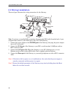
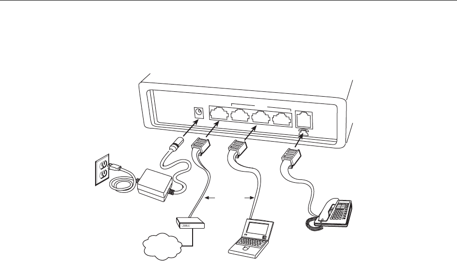
2.2 Wiring Installation
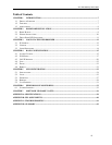
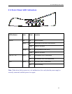
The next figure illustrates the wiring connections for the Gateway.
LAN
ADSL Router Modem
Network
Card
Port
Power Cable
04-17594
POWER
WAN
PHONE
3X
2X
1X
Internet
Ethernet
Cable
(RJ45)
Telephone Cable
(RJ11)
Telephone
PC
ADSL LAN Port
Note: If you have an installed DSL connection, disconnect the RJ45 cable from the back of your
computer and connect it to the WAN port of the 1813 VoIP Gateway.
1. Connect the power adapter to the POWER jack of the Gateway, then plug the power adapter
into an AC wall outlet.
2. Connect the WAN port of the Gateway to your DSL or cable modem’s LAN port with an
RJ45 connector cable.
3. Connect the LAN ports (1X- 3X) of the Gateway to your PC’s Ethernet port, or to an
Ethernet switch or hub, with an RJ45 cable. One is supplied with the Gateway.
4. Connect the Phone port of the Gateway to your analog telephone set with an RJ11 connector
cable.
Note 1: If the device fails to power on, or it malfunctions, first verify that the power supply is
correctly connected, and then power it on again.
Note 2: Restore the default parameters of the Gateway at any time by holding down the Reset
button for over three seconds.
10