


Peripheral Equipment
243
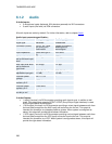
6.1.4 Data port
The data port(s) are implemented as Data Communications Equipment (DCE). The connectors
used are female 9-pin D-subs.
NOTE! Data port 2 is used by both Wave II Camera and Precision HD Camera and has different
pin-out scheme for the different use.
The TANDBERG main camera is normally connected to data port 2 and pin number 4 provides
12V DC / 1 Amps to the main camera. Otherwise the pin-outs for both data ports are the same.
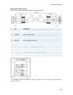
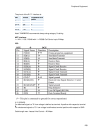
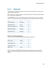
Signal name Direction Pin number
Carrier detect, CD From DCE 1
Receive data, RXD From DCE 2
Transmit data, TXD To DCE 3
Data terminal ready, DTR From DCE 4
Signal ground, GND 5
Data set ready, DSR From DCE 6
Ready to send, RTS To DCE 7
Clear to send, CTS From DCE 8
Ring indicator, RI From DCE 9
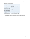
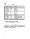
Data Port 2 with Precision HD Camera
Pin-outs for the THSI (TANDBERG High Speed Interface) on data port 2:
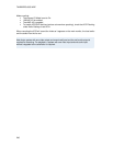
Signal name Direction Pin number
Video LVDS + To DCE 1
Receive data, RXD From DCE 2
Transmit data, TXD To DCE 3
Power, +12V 4
Signal ground, GND 5
Video LVDS - To DCE 6
NOTE! The enclosed TANDBERG Camera Cables must be used! Do not use other camera
cables as this might cause problems with the transfer of video signals from the Precision HD
Camera.