


TANDBERG 6000 MXP
14
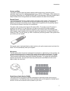
2.2 Connecting Cables
All cables needed in standard configuration are already connected to the codec. Connect these
cables to their respective parts of the system.
1. Power cable
Connect the power cable to a standard electrical outlet.
2. Monitor cables
Connect the codec's DVI output cable to the input on the monitor.
3. Microphone cable
Connect the microphone cable to the microphones.
4. Camera cable
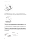
When installing the Precision HD Camera, please follow the instructions in the enclosed
Installation Sheet for TANDBERG 6000 MXP Profile. Installation Sheets are also found on the
User Manuals CD.
NOTE! The enclosed TANDBERG Camera Cables must be used! Do not use other camera
cables as this might cause problems with the transfer of video signals from the Precision HD
Camera.
If you have a WAVE II Camera: Connect the WAVE II camera cable (labeled “Main Cam”) to
the S-Video connector on the WAVE II camera. Connect the WAVE II control cable (labeled
“Camera Control”) to the RJ-45 on the camera.
5. PC cable - optional
Connect the PC cable to a PC.
6. LAN cable - optional
To connect the system to a Local Area Network (LAN), connect the cable labeled "LAN
Ethernet" to a suitable Ethernet port on the LAN.
7a. ISDN cables - using BRI interface - optional
Connect the ISDN cables to the RJ45 ISDN sockets (S/T interface) provided by the network
provider. The main ISDN number will be that number associated with the socket to which ISDN
cable number 1 has been connected.
NOTE! The system does not have a built-in network terminator. If wall socket provides an
ISDN U-interface, a NT1 between your system and the ISDN line is needed, see Appendix
10 for more information.
7b. ISDN cable - using the PRI interface - optional
If using the PRI interface, the E1/T1 cable should be connected to a CSU (Channel Service
Unit). ). It is recommended that a CSU be used between the system and the PRI line from the
network provider, see Appendix 8
.