


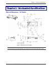

Chapter 2 – Mechanical Specifications
SocketModem Global MT5634SMI Developer’s Guide 11
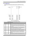
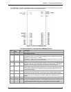
Pin Configurations
The MT5634SMI SocketModem uses a 20-pin interface to provide an on-board DAA with tip and ring
connections, audio circuit for call-progress monitoring, LED driver for call status annunciation, and serial
interface.
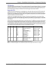
Figure 2–2. Serial SocketModems Pins
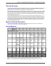
Pin Descriptions for Serial SocketModem Devices
Pin # Signal Name I/O Type Description
26 DGND
Digital Ground
33 –RTS I
Request to Send. RTS signal is used for hardware flow control.
34 –RXD O
Received Data. The modem uses the RXD line to send data received from
the telephone line to the DTE and to send modem responses to the DTE.
During command mode, –RXD data presents the modem responses to the
DTE. Modem responses take priority over incoming data when the two signals
are in competition for –RXD. When no data is transmitted, the signal is held in
mark condition.
35 –TXD I
Transmitted Data. The DTE uses the –TXD line to send data to the modem
for transmission over the telephone line or to transmit commands to the
modem. The DTE should hold this circuit in the mark state when no data is
being transmitted or during intervals between characters.
36 –RI O
Ring Indicate. –RI output ON (low) indicates the presence of an ON segment
of a ring signal on the telephone line. The modem will no go off-hook when –RI
is active; the modem waits for –RI to go inactive before going off-hook.
37 –DSR O
Data Set Ready. –DSR indicates modem status to the DTE. –DSR OFF
(high) indicates that the DTE is to disregard all signals appearing on the
interchange circuits except Ring Indicator (–RI). It reflects the status of the
local data set and does not indicate an actual link with any remote data
equipment.
38 –CTS O
Clear To Send. –CTS is controlled by the modem to indicate whether or not
the modem is ready to transmit data. –CTS ON indicates to the DTE that
signals presented on TXD will be transmitted to the telephone line. –CTS OFF