Chapter 9 – Firmware Upgrade Procedure
SocketModem Global MT5634SMI Developer’s Guide 73
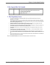
2. Other Supported Boot Code Commands
2.1 ATI0 - returns 000
2.2 ATI1 - returns boot code version number M.mmn where
M = unique code for each different platform that has boot code
mm = version number of boot code
n = version letter of the boot code
Examples: 2.05e, 2.12d
ATI4- Boot code date and time.
3. Other Programming Concerns
1. The values programmed into Addresses 0000h, 0001h and 0002h should always be forced to
C3h 00 01 (i.e., JP 100h).
This is because the boot code starts at address 100h, while all normal modem code starts at 200h. By
allowing 0000h to be programmed to a jump value other than 0100h, the boot code would be bypassed
and no further upgrades could occur.
2. Addresses 0100h-01FFh through 70000h-7FFFFh should not be allowed to be programmed under
normal circumstances, as this is the main body of the boot up code.
3. The packets sent to the modem must be presorted by address and aligned on 128 byte boundaries (i.e.,
each packet must start on an address that is a multiple of 128).
4. The packets should also be a minimum of 128 bytes with the non-programmed bytes set to the hex
value of FF.
5. The packets sent to the modem must not span a 4K boundary (i.e., start the packet before it and go
over the boundary in the middle of the packet).
6. The 10-millisecond delay between M’s at the beginning of the handshake is so that the modem can
sync up to the start bit. If the M’s are sent one right after another, a data bit might be mistaken as a start
bit.
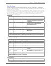
7. Multi-Tech firmware files are in Intel Hex Format and must be read in and formatted into 128-4096 byte
blocks before being sent to the modem.
Refer to the Intel Hex Format section below for information about the Intel Hex Format.


