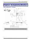
Chapter 2 – Mechanical Specifications
SocketModem Global MT5634SMI Developer’s Guide 12
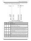
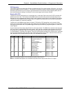
indicates to the DTE that it should not transfer data across the interface on
TXD.
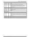
39 –DCD O
Data Carrier Detect. –DCD output is ON (low) when a carrier is detected on
the telephone line or OFF (high) when carrier is not detected.
40 –DTR I
Data Terminal Ready (Active Low). The –DTR input is turned ON (low) by
the DTE when the DTE is ready to transmit or receive data. –DTR ON
prepares the modem to be connected to the telephone line, and, once
connected, maintains the connection. –DTR OFF places the modem in the
disconnect state.
41 DGND GND
61 VCC PWR
+5V or 3.3V Supply (depends upon model).
63 AGND GND
Analog Ground. Analog ground is tied common with DGND on the
SocketModem. To minimize potential ground noise issues, connect audio
circuit return to AGND.
64 SPKR
Speaker Output. SPKR is a single ended-output. SPKR is tied directly to the
CODEC.
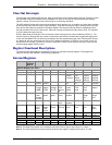
LED driver outputs are open-drain inverter-driven (74HCT05) lines with 1.5K ohms pull-up resistors. Max
output current 25 mA.
1 Tip I/O
Tip Signal from Telco.
2 Ring I/O
Ring Signal from Telco.
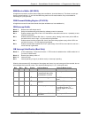
24 –RESET I
Modem Reset (with weak pull-up). The active low –RESET input resets the
SocketModem logic and returns the AT command set to the original factory defa
u
values or to "stored values" in NVRAM. –RESET is tied to VCC through a 400m
s
time constant circuit for "Power-on-Reset" functionality. The modem is ready to
accept commands within 6.5 seconds of power-on or reset. Reset must be asse
r
for 300 ns.
29 DCDIND O
Active High DCD status.
30 RXIND O
Active High RDX status
31 DTRIND O
Active High DTR status
32 TXDIND O
Active High TXD status


