


2.4.2 Digital Status Outputs
The M460H has four digital status outputs for indicating error and operational status
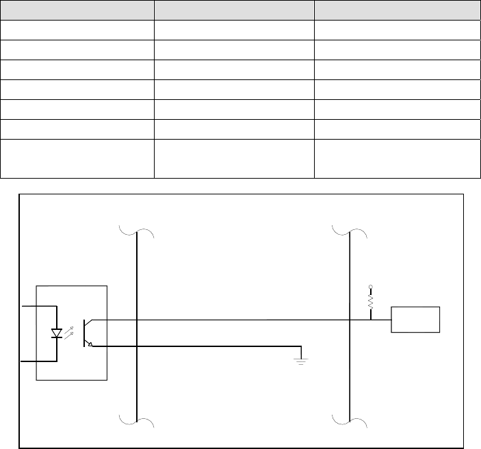
conditions. These outputs are in the form of opto-isolated open-collector transistors.
They can be used to drive status LED’s on a display panel or interface to a digital device
such as a Programmable Logic Controller (PLC).
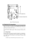
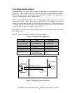
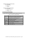
Figure 2-4 shows the most common way of connecting the digital outputs to an external
device such as PLC. Note: Most devices, such as PLC’s, have internal provision for
limiting the current that the input will draw from an external device. When connecting to
a unit that does not have this feature, external dropping resistors must be used to limit the
current through the transistor output to 50mA or less.
See Chapter 7 for details on using the Status Outputs for diagnosing sensor and system-
level malfunctions.
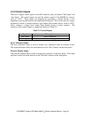
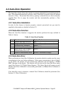
Table 2-1 below describes the function of the status outputs.
Table 2-1 Digital Status Output Pins
Label Name Operation
STATUS OUT 1 Sensor O.K. Normally On
STATUS OUT 2 Invalid Reading Normally Off
STATUS OUT 3 Lamp Low Normally Off
STATUS OUT 4 Cell Dirty Normally Off
STATUS OUT 5 Auto-Zero Error Normally Off
STATUS OUT 6 Spare Undefined
STATUS COM Common Pin for
all Status Outputs
N/A
Figure 2-4 Digital Output Connections
Opto-Isolator
Digital Output #1-4 (Collector)
Digital Output Common (Emmiter)
Ground Provided
by PLC
Programmable Logic
Controller or other device
M454
Digital
Input
+5V
P/N 03662D Teledyne API Model 460H O
3
Monitor Operator Manual - Page 15