


Installation
Page
10
Hardware Overview
Front View
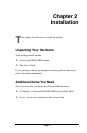
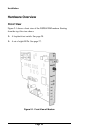
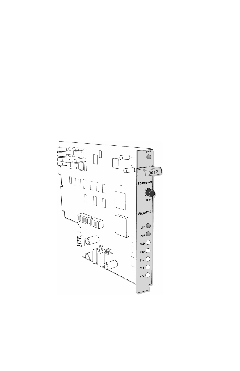
Figure 2-1 shows a front view of the DSP9612RM modem. Starting
from the top, this view shows:
c
A loopback test switch. See page 28.
c
A set of eight LEDs. See page 27.
Figure 2-1. Front View of Modem