


Hardware Overview
Page
11
Component View
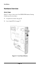
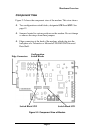
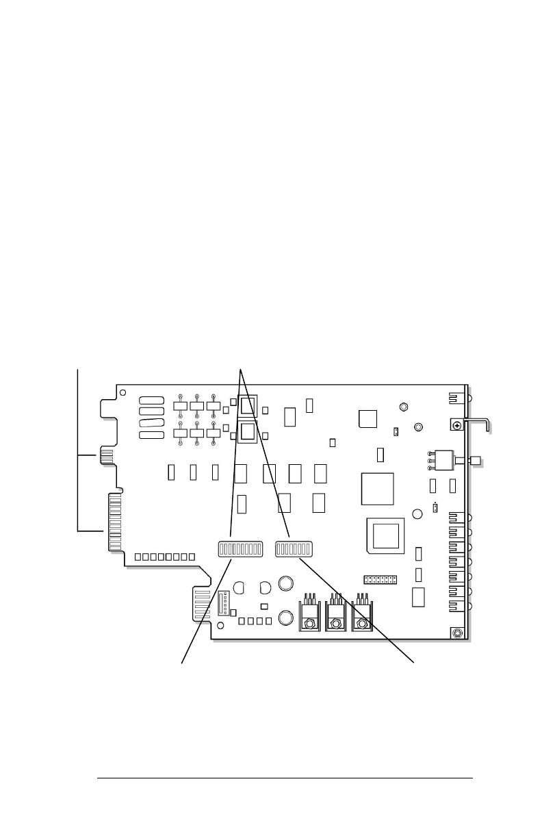
Figure 2-2 shows the component view of the modem. This view shows:
c
Two configuration switch blocks, designated
SW1
and
SW2
. See
page 12.
c
Jumpers located in various positions on the modem. Do not change
or remove the straps from these jumpers.
c
Edge connectors at the back of the modem, which plug into the
backplane of a Telenetics or Motorola/UDS RM 16M Universal
Data Shelf.
Figure 2-2. Component View of Modem
Edge Connectors
Configuration
Switch Blocks
Switch Block SW2
Switch Block SW1