


21
Intercom Channels, Balanced Mode (Both Back Panel and internal switches (BAL/
UNBAL) must be set to same setting)
Output Level: 1 Vrms nominal
Input Impedance: 300 ohms
Bridging Impedance: greater than 10,000 ohms
Sidetone: -40 dB, 35 dB adjustable range
Call Signaling:
Send: 20 kHz ±100 Hz, 0.5 Vrms ±10%
eceive: 20 kHz ±800 Hz, 100 mVrms
Mic-Kill Frequency:
Send: 24 kHz ±300 Hz, 0.5 Vrms ±10%
Detect: 24 kHz ±800 Hz, 100 mVrms
Noise Contribution: less than -70 dB
Common Mode Rejection Ratio: greater than 50 dB
Connector Type: One XLR-3M and XLR-3F pair, wired in parallel, for each channel (permits
“loop-thru” connection). Two XLR-6M (Neutrik) connectors for 2-channel connection.
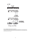
XLR-3 Balanced Configuration Pinouts
Pin 1: Common
Pin 2: Intercom audio low and +24 VDC input
Pin 3: Intercom audio high and +24 VDC input
XLR-6 Balanced Configuration Pinouts
Pin 1: Audio and DC Common
Pin 2: Local power (12 to 15 VDC, 65 to 150 mA)
Pin 3: Intercom channel 1 audio low and +24 VDC phantom power
Pin 4: Intercom channel 1 audio high and +24 VDC phantom power
Pin 5: Intercom channel 2 audio low and +24 VDC phantom power
Pin 6: Intercom channel 2 audio high and +24 VDC phantom power
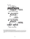
Intercom Channel, Unbalanced Mode (Both Back Panel and internal switches (BAL/
UNBAL) have to be set to same setting)
Output Level: 1 Vrms ±10%
Input Impedance: 150 ohms
Bridging Impedance: greater than 10,000 ohms
Call Signaling:
Send: 11 ±3 VDC
Receive: 4 VDC minimum
Connector Type: Uses same connectors as for balanced mode, above, but with pinouts
modified by BAL/UNBAL switch on back panel as follows: