


5
10. C
ALL KEYS: Used to place calls on intercom channels and to indicate incoming calls.
11. INTERCOM LISTEN KEYS: Momentary or latching operation possible.
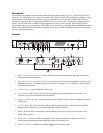
12. SPEAKER VOLUME CONTROL: The Volume control adjusts the level to the front panel speaker. If an external
speaker is used, volume must be adjusted at the external speaker.
13. COMBINE / ISOLATE SWITCH:This recessed, pushbutton switch lets you combine the audio signals of the two
channels to create a single audio channel where all users can intercommunicate. Or, you can isolate each
channel to create two groups of completely independent users. For normal operation, it should be set in the
isolate position.
14. CHANNEL STATUS INDICATORS AND RESET PUSHBUTTON:The indicators are green for normal operation and red
when there is an overload or short circuit. The Reset pushbutton restores normal operation after the
short-circuit or overload has been located and fixed.
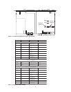
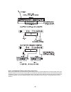
15. U
NIVERSAL AC POWER INPUT: The MS-2002 accepts any input power in the range of 100-240 VAC, 50/60
Hz.
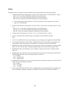
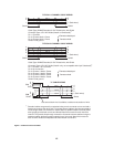
16. 2-CHANNEL INTERCOM CABLE CONNECTORS: One male and one female XLR-6 connector for
2-channel operation with SS2002, BP2002, etc.
17. PROGRAM INPUTS CONNECTOR AND TRIMMERS: Each intercom channel has its own program input and level
adjust trimmer. The program inputs may be turned on or off via the front panel and they may be set to
interrupt during talk, if desired.
18. 1- CHANNEL INTERCOM CABLE CONNECTORS: Two connectors are provided for each channel for loop-through
connection of 1-channel intercom stations, such as the SS1002, BP1002, etc.
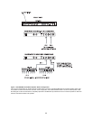
19. PA OUTPUT: Connects to a public address system.
20. EXPANSION OUT CONNECTOR: Connects to an EMS4001 Expansion Station.
21. SPEAKER OUTPUT JACKS: May be used with external, powered loudspeakers for monaural or binaural
listening configurations.
22. BALANCED / UNBALANCED SELECTOR SWITCHES: The selector switches sets the MS-2002 for compatibility
with either Audiocom or Clear-Com* channel connector pin-outs, channel power requirements, and call
signaling requirements. Both switches must be in the same position.