


9
For binaural operation with two speakers:
1. Set SW3-2 to on.
2. Set SW3-5 to off.
3. Set SW3-6 to on.
4. Set SW3-7 to off.
5. Set SW3-8 to off.
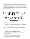
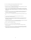
Balanced/Unbalanced Switches
Both of the BAL - UNBAL Switches on the back panel are set at the factory to the balanced (BAL) position for use
with Audiocom intercom channels. Set the switches to the unbalanced (UNBAL) position for use with a Clear-Com
intercom systems.
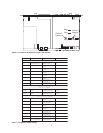
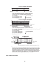
Direct Program Listen Enable / Disable Jumpers
By default, each MS-2002 program input can be heard by all intercom stations that are listening on the correspond-
ing intercom channel. This includes the MS-2002. Program input routing to the intercom channels can be turned on
or off via the MS-2002 front panel programming. (See “Turning the Program Inputs On and Off”, page .) Addition-
ally, all program signals can be routed directly to the MS-2002 speaker or headset. This lets the MS-2002 operator
hear the program inputs even if they are not being routed to the intercom channels. To disable direct program
listening in the speaker or headset for one or more program inputs, reset the appropriate jumper as shown in Table 2.
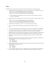
Table 2 - Direct Program Listen Enable / Disable Jumpers
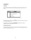
Mounting
The MS-2002 mounts in a standard 19 inch equipment rack and is 1 rack unit high. When mounting the MS-2002
install the supplied black face plates on the appropriate side. The face plates should be mounted with the groves on
the top.
Note: You will have to perform the sidetone adjustment (page ) after all components are connected. With
the MS-2002 being rack mounted, you may not be able to access the sidetone trimmers. In this case, you
can position the MS-2002 in the rack and make all required connections. Then, adjust the sidetone trim-
mers before installing and tightening all rack mount screws.
Connections
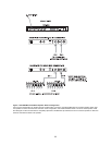
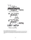
Refer to the following paragraphs, and the sample connection drawings shown in Figures 3 through 7, starting on
page 10.
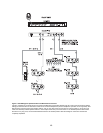
External Program Input and PA Output
Connections for external program input and PA output are shown in Figure 6, page 13. EMS4001 Expansion Station
Connection (Optional Component)
Refer to the EMS4001 User Instruction Manual for detailed connection information.
repmuJrepmuJ
repmuJ
repmuJrepmuJ noitpircseDnoitpircseD
noitpircseD
noitpircseDnoitpircseD srepmuJrofsgnitteSsrepmuJrofsgnitteS
srepmuJrofsgnitteS
srepmuJrofsgnitteSsrepmuJrofsgnitteS
3J
ottcerid1margorP
rekaepSrotesdaeH
delbanE:detrohS3&2sniP
elbasiD:detrohS2&1sniP
6J
ottcerid2margorP
rekaepSrotesdaeH
delbanE:detrohS3&2sniP
elbasiD:detrohS2&1sniP