


Texas Instruments 4Q 2006 Interface Selection Guide
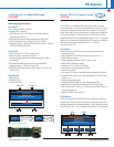
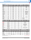
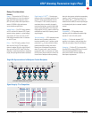
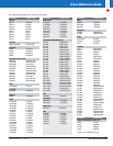
Conn. Conn. Conn. Conn. Conn. Conn.
Rcvr Rcvr Rcvr Rcvr Rcvr
Rcvr
22 Ω 22 Ω
V
TT
V
TT
0.25" 0.25".94".94".94".94"
Z
0
†
Z
0
¥
† Unloaded backplane trace natural impedance (Z
0
) is 45 Ω to 60 Ω, with 60 Ω being ideal.
¥ Card stub natural impedance (Z
0
) is 60 Ω.
1" 1" 1" 1" 1" 1"
Slot 1 Slot 2 Slot 3 Slot 18 Slot 19 Slot 20
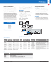
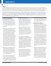
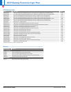
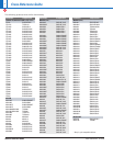
TI
Competitor A
2
1.5
1
0.5
0
1.98E-08 4.48E-08
Time
6.98E-08
Volts
Design Considerations
P
rimary
Speed — The speed of the GTLP family in
p
arallel backplanes is 4x that of traditional
logic. Optimized output edge-rate control
(OEC™) circuitry allows clock frequencies in
excess of 100 MHz in high-performance
system backplane applications.
Voltage Range — The GTLP family operates
at 3.3 V and with 5-V tolerant LVTTL inputs/
outputs and can operate in a mixed-voltage
environment. GTLP acts as LVTTL-to-GTLP
bi-directional translators with 5 V tolerance
on the LVTTL port.
Drive — The GTLP family provides ±24-mA
drive on the A-Port (LVTTL side) and the
choice of medium (50 mA) or high (100 mA)
drive on the B-Port (GTLP side). This offers
flexibility in matching the device to backplane
length, slot spacing and termination resistance.
S
ignal Integrity–TI-OPC
™
—
Overshoot pro-
tection circuitry was designed specifically for
t
he GTLP family and incorporated into the
GTLP outputs. TI-OPC actively clamps any
overshoots that are caused by improperly
terminated backplanes, unevenly distributed
cards or empty slots. OEC on the rising and
falling edge of the GTLP outputs reduces line
reflections and extra EMI, improving overall
signal integrity.
True Live Insertion — GTLP backplane drivers
allow for Level 3 isolation and true live-
insertion capability. Level 1 isolation, partial
power-down: I
O
FF
circuitry within the device
prevents damage by limiting the current
flowing from an energized bus when the
device V
CC
goes to zero. Level 2 isolation,
hot insertion: both I
OFF
and power-up 3-state
(PU3S) circuitry allow insertion or removal of
a board into a backplane without powering
down the host system and without suspending
signaling. Level 3 isolation, live insertion: for
l
ive insertion both I
O
FF
a
nd PU3S circuitry are
needed and the board I/Os must be precharged
to mid-swing levels prior to connector insertion/
removal.
Secondary
Compatibility — GTLP provides an easy
migration path from traditional backplane logic
like ABT, FCT, LVT, ALVT, LVC and FB+.
Portfolio — TI offers the broadest GTLP
portfolio in the industry, with both high-drive
(100 mA) and medium-drive (50 mA) devices.
Packaging — TI offers GTLP in a low-profile,
fine-pitch BGA package (LFBGA) and in a quad
flat no-lead package (QFN) for higher
performance and the ultimate reduction in
board-space requirements.
Single Bit Representation of a Multipoint Parallel Backplane
Signal Integrity: TI vs Competition
GTLP (Gunning Transceiver Logic Plus)
39
➔