


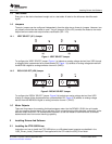
3.3UpdatingDACOutputforCurrentControl(VREF/DECAY)
VREF=DAC_VALUE ·
2.5 V
¾
4095
(1)
3.4UpdatingDACOutputforDecayControl(DECAY)
DECAY=DAC_VALUE ·
2.5 V
¾
4095
(2)
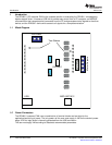
3.5OperatingtheStepperMotor
3.5.1TurningtheStepperMotor
WindowsApplication
www.ti.com
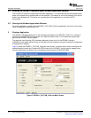
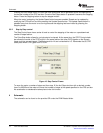
AcheckedcheckboxtranslatestoaHIlevelontherespectivecontrolsignal.Aun-checkedcheckbox
translatestoaLOlevelontherespectivecontrolsignal.
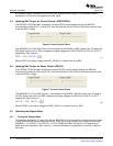
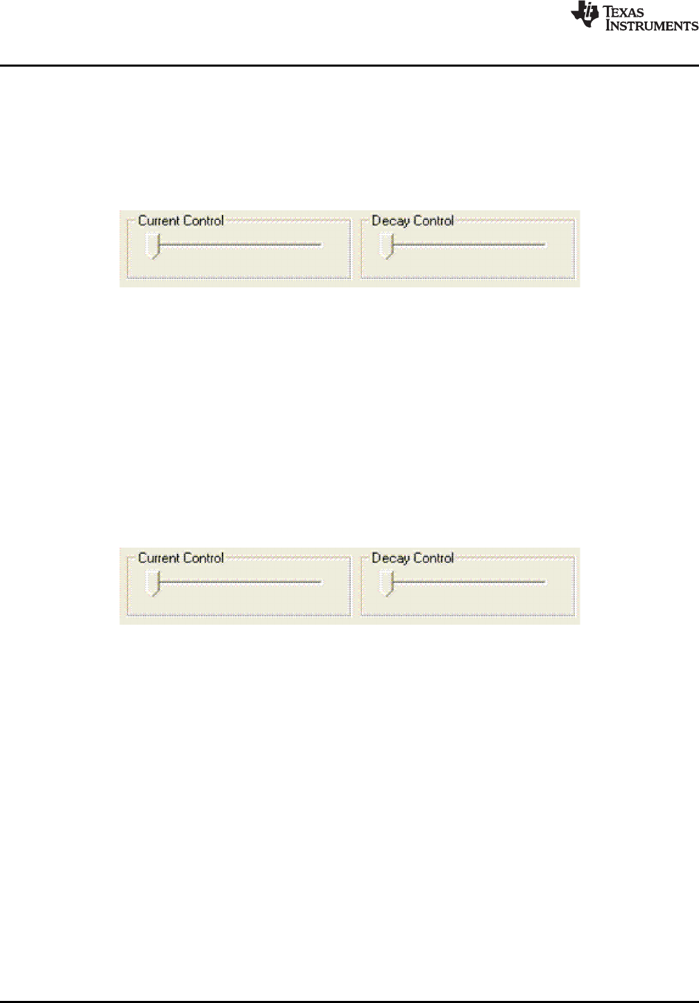
IftheDRV8811EVMhasbeenconfiguredtoacceptVREFanalogvoltagesthroughtheMSP430
microcontrollerinterface(JP1issettoINT),thenthesliderbarontheCurrentControlframecanbeused
tosettheVREFvoltage.
Figure6.CurentControlFrame
TheMSP430F161212-bitDACchannel0isconnectedtotheDRV8811VREFanaloginput.Changingthe
DACdigitalvaluefrom0to4095,changestheanalogvoltageattheVREF/DECAYpinfrom0Vto2.5V
respectively.SeeEquation1.
WhereVREFistheoutputvoltageandDAC_VALUEisanumberfrom0to4095.
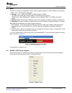
IftheDRV8811EVMhasbeenconfiguredtoacceptDECAYanalogvoltagesthroughtheMSP430
microcontrollerinterface(JP6issettoINT),thenthesliderbarontheCurrentControlframecanbeused
tosettheDECAYvoltage.
Figure7.CurrentControlFrame
TheMSP430F161212bitDACchannel1isconnectedtotheDRV8811DECAYanaloginput.Changing
theDACdigitalvaluefrom0to4095,changestheanalogvoltageattheDECAYpinfrom0Vto2.5V
respectively.SeeEquation2.
WhereDECAYistheoutputvoltageandDAC_VALUEisanumberfrom0to4095.
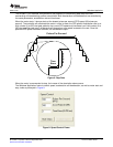
TheWindowsApplication,inconjunctionwiththeMSP430F1612microcontroller,utilizesaseriesoftimers
tocoordinatetherateofstepssenttothedevice.Onceallthecontrolsignalsareconfiguredaccordingly
(ENABLEn=LO,SLEEPn=HI,RESETn=HI;DIR,USM0andUSM1canbeHIorLOdependingon
preferredmodeofoperation;SRnmustbeL,ifexternaldiodesarenotpopulated),themotorisreadyto
beturned.
10LaserandMotorDrivesSLVA344A–July2009–RevisedSeptember2009
SubmitDocumentationFeedback