


1.3TestStakes
1.4Jumpers
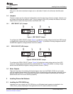
1.4.1VREFSELECT(JP1)Jumper
(a) (b)
POT
INT
POT
INT
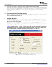
1.4.2DECAYSELECT(JP6)Jumper
(a) (b)
POT
INT
POT
INT
1.5MotorOutputs
2InstallingDriversAndSoftware
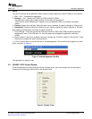
2.1InstallingtheFTDIUSBDriver
www.ti.com
InstallingDriversAndSoftware
Everypinonthedevicehasbeenbroughtouttoateststake.Alabelonthesilkscreenidentifieseach
signal.
Threepinjumperscanbeconfiguredindependentlyfromtheothertwoorthreepinjumpers.However,two
pinjumpersmusteitherbeclosedoropen.Twopinjumpers(JP2toJP5)connectthediodestothemotor
outputsandareusedunderasynchronousrectification(SR=LO).
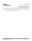
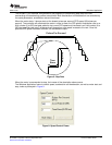
Figure1.VREFSELECTJumper
ToconfiguretheVREFSELECTjumper:Figure1(a)selectsananalogvoltagederivedfromVDDthrough
avoltagedividerimplementedasapotentiometerR4.Figure1(b)selectsananalogvoltagederivedfrom
theMSP430’sdigitaltoanalogconverterchannel0(DAC0).
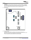
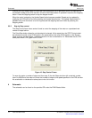
Figure2.DECAYSELECTJumper
ToconfiguretheDECAYSELECTjumper:Figure2(a)selectsananalogvoltagederivedfromVDD
throughavoltagedividerimplementedasapotentiometerR6.Figure2(b)selectsananalogvoltage
derivedfromtheMSP430’sdigitaltoanalogconverterchannel1(DAC1).
TherearethreewaysofconnectingthebipolarsteppermotorintotheDRV8811EVM:fourpinheader
(J2),fourpositionterminalblock(J3)ortestclips.Eachconnectionstyleoffersidenticalconnectivitytothe
device’soutputterminals.Itisrecommended,however,tousetheheaderorterminalblock,asthetest
stakestracesareoflowcurrenthandlingcapability.
InstructionsonhowtoinstalltheFTDIUSBdriveronaWindowsbasedcomputeraredetailedinthe
“USB_Drivers_Install_Readme.pdf”filesuppliedwiththeCDinsidetheUSB_Driverfolder.
SLVA344A–July2009–RevisedSeptember2009LaserandMotorDrives7
SubmitDocumentationFeedback