


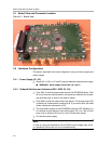

2-1
Quick Start
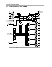
Quick Start
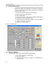
In order to setup the EVM quickly and to take some measurements at default
settings, the following actions are required:
- Supply 3.3 V to P1, LED D4 will be on.
- Apply a single-ended reference clock to the reference clock input
PRI_REF (pin A1) or SEC_REF (pin B1). For default setting, the reference
clock must be 1/8
th
of the VC(X)O frequency. If REF_SEL is set to 1, then
PRI_REF is selected. If REF_SEL is set to 0, then SEC_REF is selected.
This selection can be realized via J26 (header 1 and 2 is high; header 2
and 3 is low).
- Connect Y0/Y0B (or Y1/Y1B) to oscilloscope in order to check an output
signal. Ensure the oscilloscope has 50 Ω to ground termination.
After power up, D1 is on if there is a valid reference clock and D2 is on if there
is a valid VC(X)O clock for the CDCM7005. If D3 turns on, then the reference
clock and the VC(X)O clocks are phase locked.
Chapter 2