


Application Circuit Diagram
5-2
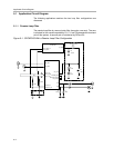
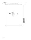
5.1 Application Circuit Diagram
The following applications sections the two loop filter configurations are
discussed.
5.1.1 Passive Loop Filter
The passive loop filter is a second order filter (two poles, one zero). The zero
is required for the overall loop stability. R1, C1, and C2 generate the dominant
pole of the system. A second pole is introduced by R2 and C3.
Figure 5−1. CDCM7005 With a Passive Loop Filter Configuration
SPI
PECL_OUT_B
PECL_OUT
V_CTRL
VC(X)O
CP_OUT
VC(X)O_IN
VC(X)O_IN_B
CTRL_LE
CTRL_DATA
CTRL_CLK
PRI_REF
YnB
YnA
CDCM7005
PLL_LOCK
STATUS_VC(X)O
STATUS_REF
Low-Pass Filter
R1
4.7 kΩ
C3
100 nF
R2
160 Ω
C2
100 nF
C1
22 µF
10 nF10 nF
10 nF
R
150 Ω
R
150 Ω
R
82 Ω
R
82 Ω
130 Ω
V
CC
V
CC
130 Ω
SEC_REF
491.52 MHz