


System Features Selection
1-5
PCI445X Device
1.1.10 Socket Activity LEDs
Socket activity signals can be assigned on MFUNC4 (slot 1), MFUNC3 (slot 2),
MFUNC5 (OHCI_LED), MFUNC6 (OHCI_LED), and MFUNC7 (OHCI_LED).
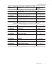
1.1.11 MFUNC7–MFUNC0 Terminal Assignments
After selecting required functions for the system, multifunction terminals
MFUNC7–MFUNC0 are ready to be assigned. Texas Instruments offers
Windows-based software, named TIROUTE.EXE, to assist with terminal
assignment.
1.1.12 Miscellaneous Functions Description
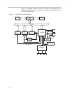
1.1.12.1 Serialized Interrupt Control
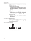
Serialized interrupt signaling is described below.
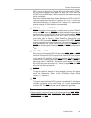
Figure 1–2. Serialized Interrupt Signal
IRQ0 IRQ1 SMI IRQ3 IRQ4 IRQ5 IRQ6 IRQ7 IRQ8 IRQ10 IRQ11 IRQ12
IRQ13 IRQ14 IRQ15IOCHCK INTA INTB INTC INTD STOP Frame
START Frame
PCLK
IRQSER
PCLK
IRQSER
The start frame width may vary from four to eight PCI clock cycles. The STOP
frame width is two clock cycles for quiet mode and three clock cycles for
continuous mode. Default mode is continuous mode for all slave devices and
a host device. PIIX4 does not support IRQ0, IRQ8, and IRQ13.
The PCI445X can generate serial IRQ frames for ISA and PCI interrupts.
Below are related registers and their definitions.
- INTMODE bits (device control register, PCI offset 92h, bits 2–1). Select
interrupt mode
- SER_STEP bits (system control register, PCI offset 80h, bits 31–30).
Change PCI interrupt data frame (serial interrupts only)
- INTRTIE bit (system control register, PCI offset 80h, bit 29). Tie CardBus
PCI interrupts to INTA
- TIEALL bit (system control register, PCI offset 80h, bit 28). Tie all PCI
interrupts internally
Refer to the
Serialized IRQ Support for PCI Systems
specification,
revision 6.0.
1.1.12.2 CSC Interrupt Routing for Windows Compatibility
The CSC interrupt routing control bit (diagnostic register, PCI offset 93h, bit 5)
should be set to 1 (default) to keep Windows compatibility.