


System Implementation
1-19
PCI445X Device
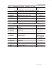
1.4 BIOS Considerations
1.4.1 Initialization
This section explains which registers require initialization, but does not
discuss detailed information about the registers themselves. Refer to the
corresponding specifications.
Reference white paper:
http://www.microsoft.com/hwdev/busbios/cardbus1.htm
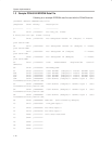
1.4.1.1 PCI Standard Registers Initialization
- Command register (PCI offset 04h: 16-bit)
Set to 0007h (enables bus master control, memory space control, and I/O
space control)
- Cache line size register (PCI offset 0Ch: 8-bit)
Set to 08h (It is dependent on host-to-PCI bridge specification). It enables
memory read line and memory read multiple command.
- Latency timer (PCI offset 0Dh: 8-bit)
This register should reflect each PC Card requirement, but Windows does
not do so. Therefore, system imlementers should determine the value. A
detailed description of this register is in the
PCI Local Bus Interface
Specification
. Typical setting for this register is 40h.
- CardBus socket registers/ExCA base address (PCI offset 10h: 32-bit)
It should be set to 0000 0000h (default).
- CardBus latency timer register (PCI offset 1Bh: 8-bit)
Setup of this register is not required because the CardBus bus is a
single-device bus, and the PCI445X device does not deassert CGNT until
a transaction is finished. (It does not mean that the PCI445X device
continues the transaction. The PCI445X device would terminate and
disconnect or abort the transaction as required).
- Memory and I/O windows (PCI offset 1Ch – 3Fh)
All memory and I/O windows should be closed (set to base > limit).
- Interrupt line register (PCI offset 3Ch: 8-bit)
This register is set to FFh (default).
- Subsystem vendor ID and subsystem ID registers (PCI offsets 40h
and 42h: 16-bit/16-bit)
These registers can be set through EEPROM or BIOS. These registers
are read-only as default. Before writing to the registers, the SUBSYSRW
bit (system control register, PCI offset 80h, bit 5) should be set to 1. After
setting up the registers, the SUBSYSRW bit should be set 0 to protect