System Implementation
1-9
PCI445X Device
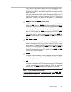
IDSEL, there is no alternative. If another AD line is to be used for IDSEL,
then the system designer must leave the pullup off LATCH and use
MFUNC7 to route IDSEL. Also, if AD23 is used, then the resistive coupling
should not be used.
Refer to the
Implementation Note: System Generation of IDSEL
in the
PCI
Local Bus Specification, Revision 2.2 (section 3.2.2.3.5)
.
PCI Local Bus
Specification, Revision 2.2 (section 4.2.6, footnote 31)
recommends
resistive coupling. A 100-Ω resistor is recommended.
- PRST (PCI reset) and G_RST (Global reset)
G_RST initializes all of the registers and state-machines of the PCI445X
device, and PRST does not. G_RST should be asserted during power-on
and rebooting. It puts the PCI445X device into the initialized state. PRST
does not initialize global-reset-only bits and, if PME is enabled, PME
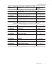
context bits. Refer to Table A–1, Global Reset Only Cleared Bits, and
Table A–2, PME Context Bits
. PRST is connected to PCI RESET; G_RST
requires a special signal in the motherboard. It will come from the chipset.
If the system does not support wake-up from D3
cold,
then PRST and
G_RST can be tied together. Note that G_RST and PRST are clamped to
V
CCP.
-
INTA, INTB, and INTC
When using one of the parallel PCI interrupt modes, INTA, INTB, and INTC
should be connected to the PCI interrupt lines. If the INTRTIE bit (system
control register, PCI offset 80h, bit 29) is set, then both CardBus functions
(functions 0 and 1) will signal and report INTA
, and only INTA and INTC will
need to be routed. If the TIEALL bit (system control register, PCI offset
80h, bit 28) is set, then all functions (0, 1, and 2) will report INTA and INTA
will be the only interrupt required.
- CLKRUN
This signal is optional. However, if saving power is a concern, this signal
should be implemented. Refer to the
PCI Mobile Design Guide
Revision 1.1 (Section 2)
.
- PME
This signal is required for the ACPI systems. In a notebook PC, this signal
is usually connected to the south bridge (ex., PIIX4) or embedded
controller (EC). The PME
terminal uses an open-drain type buffer.
Note: Pullup Resistor Requirements
A pullup resistor is required for each of the following terminals: IRDY, TRDY,
FRAME, STOP, DEVSEL, PERR, SERR, LOCK, PRST, G_RST, INTA, INTB,
INTC, CLKRUN, and PME.


