


360050398
Toshiba Corporation Digital Media Network Company
Page 128 of 157
© 2005, Copyright TOSHIBA Corporation All Rights Reserved
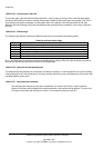
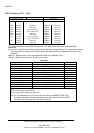
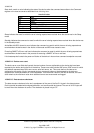
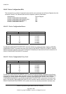
State shall contain a value indicating the state of the device when the command was written to the Command
register or the reset occurred as described in the following table.
State field values
Value State
x0h Unknown
x1h Sleep
x2h Standby
x3h Active/Idle with BSY cleared to zero
x4h Executing SMART off-line or self-test
x5h-xFh Reserved
The value of x is vendor specific and may be different for each state.
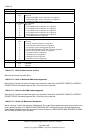
Sleep indicates the reset for which the error is being reported was received when the device was in the Sleep
mode.
Standby indicates the command or reset for which the error is being reported was received when the device was
in the Standby mode.
Active/Idle with BSY cleared to zero indicates the command or reset for which the error is being reported was
received when the device was in the Active or Idle mode and BSY was cleared to zero.
Executing SMART off-line or self-test indicates the command or reset for which the error is being reported was
received when the device was in the process of executing a SMART off-line or self-test.
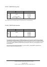
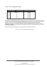
Life timestamp shall contain the power-on lifetime of the device in hours when command completion occurred.
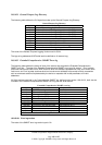
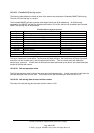
10.8.43.2.4 Device error count
The device error count field shall contain the total number of errors attributable to the device that have been
reported by the device during the life of the device. These errors shall include UNC errors, IDNF errors for which
the address requested was valid, servo errors, write fault errors, etc. This count shall not include errors
attributed to the receipt of faulty commands such as commands codes not implemented by the device or
requests with invalid parameters or invalid addresses. If the maximum value for this field is reached, the count
shall remain at the maximum value when additional errors are encountered and logged.
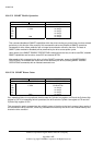
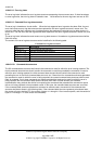
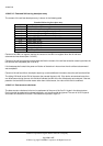
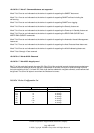
10.8.43.2.5 Data structure checksum
The data structure checksum is the two’s complement of the sum of the first 511 bytes in the data structure.
Each byte shall be added with unsigned arithmetic, and overflow shall be ignored. The sum of all 512 bytes will
be zero when the checksum is correct. The checksum is placed in byte 511.