


41
4300 Series Ancillary Cabinets Installation and Operation Manual
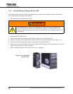
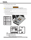
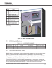
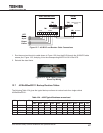
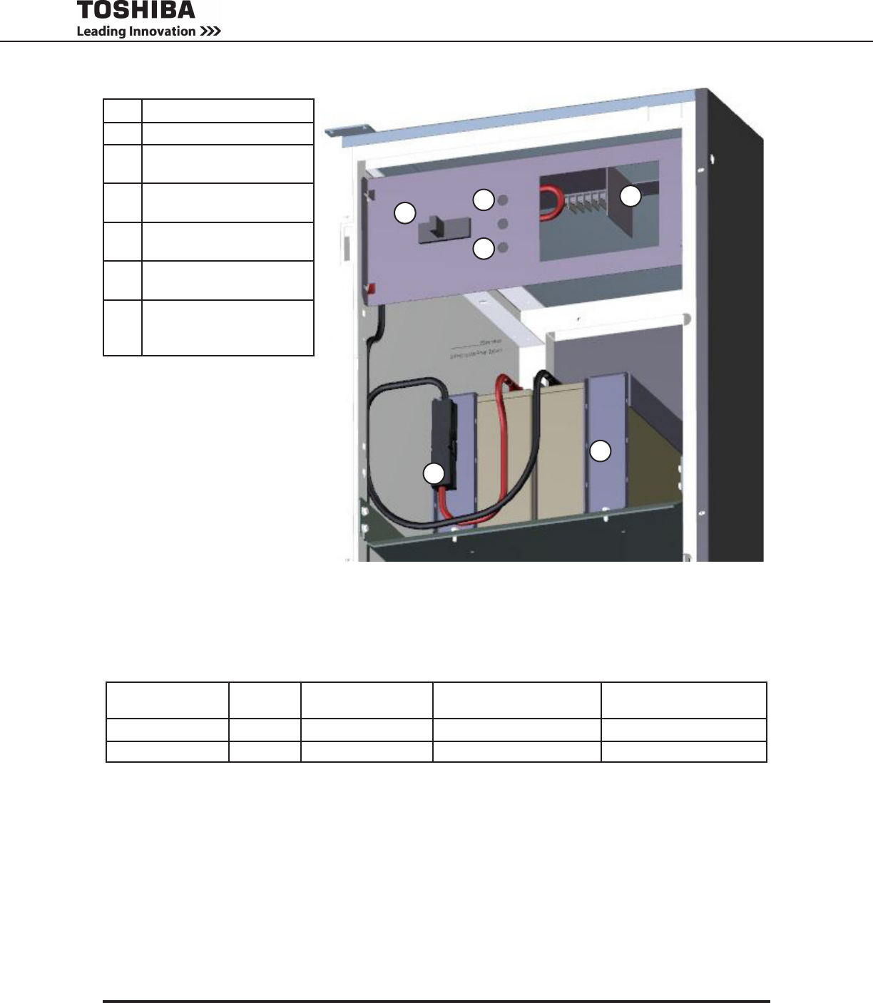
No. Part
4 Battery Retention Strap
5 MCCB - Battery Cabinet
Breaker
+ MCCB Positive Lug,
Battery Cabinet DC Out
– MCCB Negative Lug,
Battery Cabinet DC Out
6 Access for Battery Cabi-
net Output Lugs
7 Anderson Connectors for
Battery String Discon-
nect (1 set per shelf)
(All cabinets are O’Brien Black
(Textured))
Figure 12.2 Battery Cabinet MCCB Detail
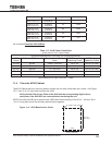
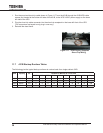
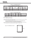
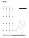
12.1 431B Estimated Runtimes
TABLE 12.1 431B ESTIMATED RUNTIMES
Battery Cabinet
Part Number*
UPS Rat-
ing
DC Bus Nominal
Voltage
Batteries/Circuit Breaker
Conguration
Battery Runtime in Min.
@ Full Load, 0.8 PF
431B30017ER111 30 kVA 288 VDC 1 Breaker, 1 Battery String 017 – 17 min. runtime
431B30008ER111 50 kVA 288 VDC 1 Breaker, 1 Battery String 008 – 8 min. runtime
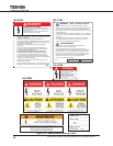
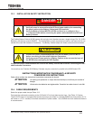
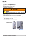
12.2 EQUIPMENT WARNING LABELS
DO NOT attempt to install, operate, maintain or dispose of this equipment until you have read and under-
stood all of the product warnings and user directions that are contained in this instruction manual.
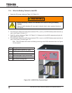
FIgure 12-2 shows examples of warning labels that may be found attached to the equipment. DO NOT
remove or cover any of the labels. If the labels are damaged or if additional labels are required, contact
your TOSHIBA representative for additional labels.
The following are examples of the warning labels that may be found on the equipment. The labels are
there to provide useful information or to indicate an imminently hazardous situation that may result in seri-
ous injury, severe property and equipment damage, or death if the instructions are not followed.
+
–
5
6
4
7