


65
4300 Series Ancillary Cabinets Installation and Operation Manual
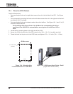
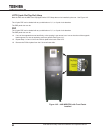
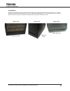
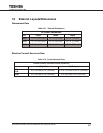
Completion
Whenthekickplatesareproperlyinstalled,thefrontpanelwillbenearlyushwiththefront(Figure13-4).Theside
kick plate will be inset about a quarter inch from the vertical side plane (Figure 13-5), and the back F/B kick plate will
extend out about a quarter inch beyond the vertical back plane of the UPS (Figure 13-6).
Figure 15-4
Front Kick Plate
Figure 15-5
Side Kick
Plate
Figure 15-6
Back Kick Plate