


61
4300 Series Ancillary Cabinets Installation and Operation Manual
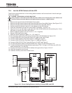
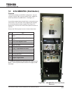
14 431A MBS/PDU (Distribution)
Purpose
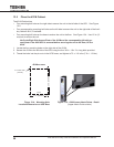
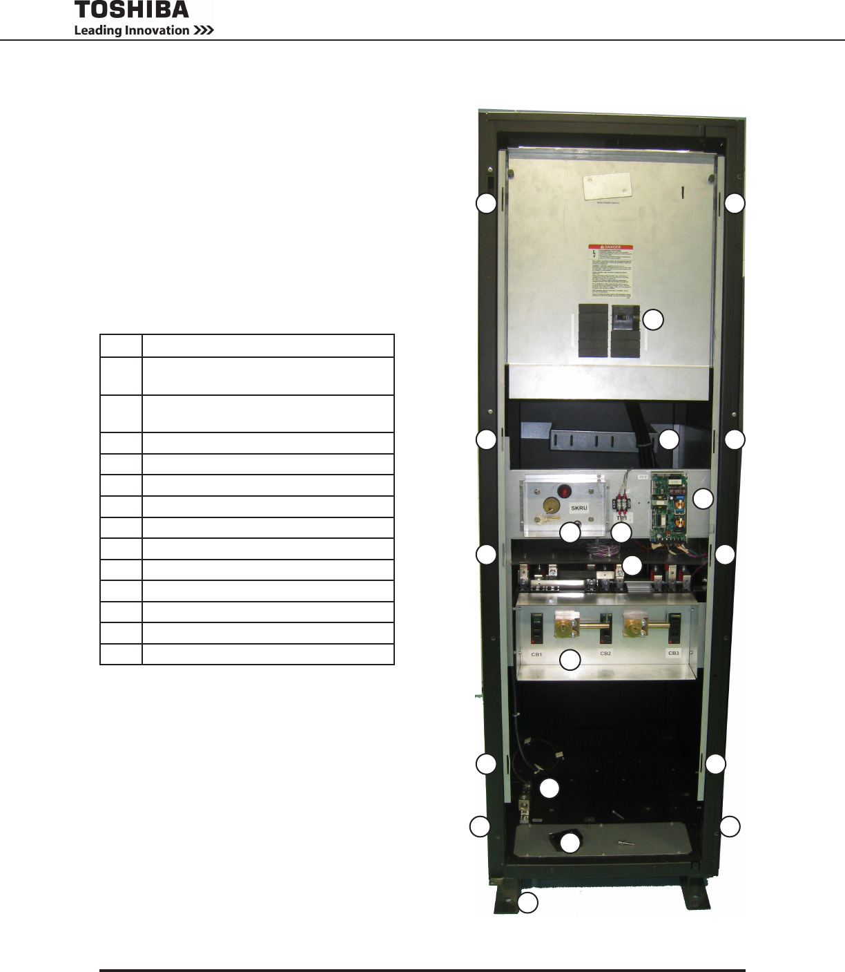
The431AisavailableinaMPS/PDUconguration.Thisunit
consiss of 12-pole PDU in the top section, and a SKRU (So-
lenoidKeyReleaseUnit)MBSbelowit.Seegure14.1.
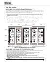
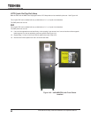
Ifoneofthemagnetsdoesnotlatchrmly,orthespacingistoo
narrow, bend one or the other of the magnetic latch supports
inoroutasrequiredtoensureagoodt.SeeFigure14-1.
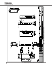
Repeat Step 14-3 and 14-4 for the F/B kick plate at the back of
the UPS.
Remove the F/B kick plates from the C-channel base skids.
No. Part
1 Upper (PPD) Front Cover Mounting
Slots
2 Lower (MBS) Front Cover Mounting
Slots
3 PDU Circuit Breaker Panel
4
1
Cable Anchor Brace
5 SKRU for MBS
6 TB1
7 PCB1 - Power Board for SKRU
8 MBS Bus Stubs
9 MBS with Keyed Mechanical Lockout
10 Ground Bus Strip
11 Side Cable Access
12 Bottom Cable Access
13 C-Channel Base
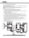
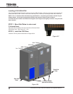
1 - Secure the cables with cable ties to the Cable Anchor
Brace. This will provide strain relief for the upper power
bus strips.
4
3
5
8
7
6
9
13
11
10
12
1 1
1 1
2 2
2 2
11
Figure 14-1 - 4400 MBS/PDU with Front Panels
Removed