44
4300 Series Ancillary Cabinets Installation and Operation Manual
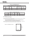
TABLE 12.2 - 431B POWER CABLE SIZES
(Cable sizes for 75°C Copper Cable)
Recommended/Maximum Wire size and Torque Requirement
UPS
Rating
Maximum DC
Current
Batt Cab
MCCB
Recommended Cable
Sizes
UPS Terminal
Lug Tightening
Torque
431B MCCB Lug
Tightening
Torque
30 kVA 127 Adc 150 A
#1 AWG – 350 kcmil
200 lb-in 225lb-in(25N•M)
50 kVA 214 Adc 250 A
250 kcmil – 350 kcmil
200 lb-in 225lb-in(25N•M)
* Wire capacity for DC lugs is 350 kcmil - 6 AWG,
TABLE 12.3 - 431B MCCB CONNECTIONS
Battery Cab
Capacity
MCCB
Rating
Lug Cable
Capacity
Condutors
per Lug
Strip
Length
Lug Torque
30 kVA 150 A #4 AWG - 4/0 1 1 in. 225lb-in(25N•M)
50 kVA 250 A 3/0 - 350 kcmil 1 1 in. 225lb-in(25N•M)
Go to Section 12.4
12.4 Place the 431B Cabinet
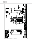
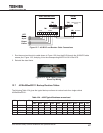
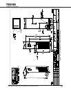
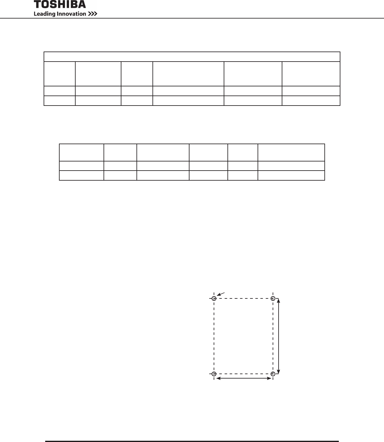
The 431B Cabinet has four mounting holes to anchor the unit after is has been set in place. See Figure
12-4. Use 1/2 in (12 mm) bolts to anchor the 431B.
Verify the Left Side Access Plate of the 431B and the corresponding Right side ac-
cess plate of the 4300 UPS are removed before anchoring the unit.
NOTE:Ensurethe431BcanbejoinedtotheUPSbeforenalanchoringofthe431A.Usefour3/8in.
-16 x 2 in long bolts to bolt the ancillary cabinet frames together. See Section 12.5.
Back
Front
4 x 0.63 in. Dia. (16 mm)
19.0 in. (483 mm)
26.7 in..
(677 mm)
Figure 12-4 - 431B Base Anchor Points


