


User’s Manual 2-1
Satellite A200/Satellite Pro A200
Chapter 2
The Grand Tour
This chapter identifies the various components of your computer. Become
familiar with each component before you operate the computer.
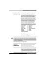
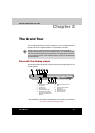
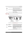
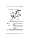
Front with the display closed
The following figure shows the computer front with its display panel in the
closed position.
* The availability of this feature is dependent on the model you purchased.
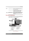
Front of the computer with display closed
Certain types of notebook chassis are designed to accommodate all
possible configurations for an entire product series. Your selected model
may not have all the features and specifications corresponding to all of the
icons or switches shown on the notebook chassis, unless you have selected
all those features.
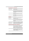
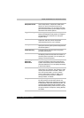
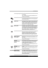
1. FRONT EDGE LOGO*
2. DC IN LED
3. P
OWER LED
4. B
ATTERY LED
5. H
ARD DISK DRIVE LED
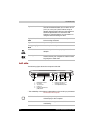
6. M
ULTIPLE DIGITAL MEDIA
C
ARD SLOT ACCESS LED*
7. W
IRELESS COMMUNICATION
S
WITCH*
8. W
IRELESS COMMUNICATION
LED*
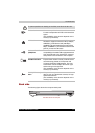
9. M
ULTIPLE DIGITAL MEDIA
C
ARD SLOT*
10. M
ICROPHONE JACK
11. HEADPHONE JACK
12. VOLUME CONTROL
6
87 9
3 42 5
10 11 12
1