


1. OUTLINE EO10-33013B
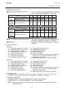
1.5 ELECTRONICS SPECIFICATIONS
1- 8
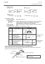
XON/XOFF (DC1/DC3) protocol + READY/BUSY (DTR) protocol
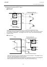
• When initialized after power on, this printer becomes ready to receive data and converts the
DTR signal to "High" level (READY). The printer sends an XON code (11H).
• When the free area in the receive buffer are 10K bytes or less, the printer converts the DTR
signal to "Low" level (BUSY) and sends an XOFF code (13H).
• When the free area in the receive buffer are 512KB or more, the printer converts the DTR
signal to "High" level (READY) and sends an XON code (11H).
• When there is no free area in the receive buffer, the printer discards received data which
exceeds the receive buffer capacity without storing it in the buffer. (After detecting the XOFF
code or BUSY signal, the host computer must stop transmission before the printer receive
buffer becomes full.)
• The printer sends an XOFF code (13H) at power off time.
• The RTS signal is always “High” level.
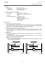
READY/BUSY (RTS) Protocol
• When initialized after power on, this printer becomes ready to receive data and converts
the RTS signal to "High" level (READY).
• The printer converts the RTS signal to “Low” level (BUSY) when the free area in the
receive buffer amount to 10K bytes or less.
• The printer converts the RTS signal to “High” level (READY) when the free area in the
receive buffer amount to 512KB or more.
• When there is no free area in the receive buffer, the printer discards received data which
exceed the receive buffer capacity without storing it in the buffer. (After detecting a
BUSY signal, the host computer must stop transmission before the printer receive buffer
becomes full.)
• The DTR signal is always “High” level (READY).
• The host should keep the DSR signal “High” level.
NOTE: Be sure to select the READY/BUSY (RTS) protocol when controlling the flow between
the Windows. Also, be sure to select “Hardware” for the flow control in the Windows
communication port setting.
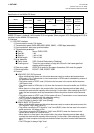
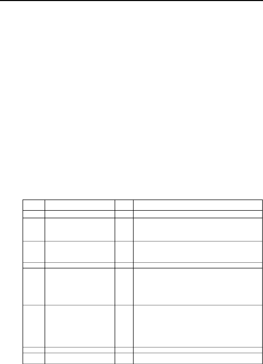
k Pin description
Pin No. Signal I/O Description
1 FG (Frame Ground) --- Ground line for circuit protection.
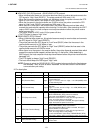
2 RD (Received Data) Input
Data line from which the printer receives data from the host
(receive data line).
Logic “1” is “Low”, and “0” is “High”. It is LOW (MARK) while
no data is being sent.
3 TD (Transmit Data) Output
Data line from which the printer sends data to the host (send
data line).
Logic “1” is “low”, and “0” is “High”. It is LOW (MARK) while
no data is being sent.
4 CTS (Clear to Send) Input Input signal from the host. This printer ignores this signal.
5 RTS (Request to Send) Output
Output signal to the host.
When READ/BUSY (RTS) protocol is selected,
this signal means READY to receive data.
When the receive buffer is nearly full, the signal turns to
“Low”, and “High” when nearly empty.
In case of other protocol is selected, this signal is always
“High” level after the power is turned on.
6 DTR (Data Terminal Ready) Output
Output signal from the printer.
When READY/BUSY (DTR) or XON/XOFF
(DC1/DC3)+READY/BUSY (DTR) is selected, this signal
means READY to receive data.
When the receive buffer is nearly full, the signal turns to
“Low”, and “High” when nearly eimpty.
In case of XON/XOFF (DC1/DC3) or READY/BUSY (RTS),
this signal is always “High” level after the power is turned on.
7 SG (Signal Ground) --- Ground line for all data and control signals.
20 DSR (Data Set Ready) Input
Input signal from the host. It must be “High” for the printer to
receive data.