


© 2006 - 2008 TOSHIBA TEC CORPORATION All rights reserved GD-1220/1221
ELECTRICAL CIRCUITS
4 - 11
4
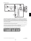
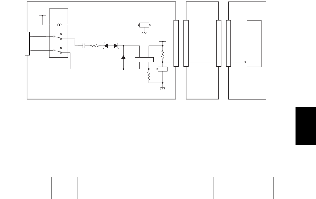
EU/AU/AS/C models
Fig. 4-11
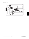
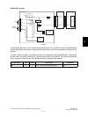
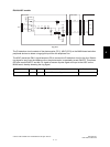
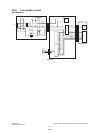
The CI detection circuit consists of the photocoupler (PC1), ASIC (IC23) on the MAIN board and other
peripheral devices to detect a ring signal input from the telephone line.
The ASIC makes the CML1 signal become LOW to connect the CI detection circuit to the line. When a
ring signal is input from the telephone line, the photocoupler is repeatedly turned ON/OFF. This allows
Q5 to be turned ON/OFF and the CI1 signal to become a pulse signal and input to the ASIC on the
MAIN board, thereby detecting the ring signal.
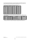
Signal Name Type Active Description Destination
CI1 I - Line 1 CI Detection Signal IC23
CN3
Lb
La
Line
0
1
0
10
3
121
4
9
1
+12V
RLY3
CML relay
CML1
Q4
3
4
3
3
27
6517
NCU board FAX board
IC23
ASIC
CI1
17
1
2
4
3
AG
Q5
SG
5VPS
R34
R35
CN4
CN262
PC1
ZD3ZD2C8 R4
D2
CN5
CN5
27
65
144
162
MAIN board