


© 2006 - 2008 TOSHIBA TEC CORPORATION All rights reserved GD-1220/1221
ELECTRICAL CIRCUITS
4 - 13
4
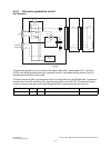
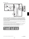
EU/AU/AS/C models
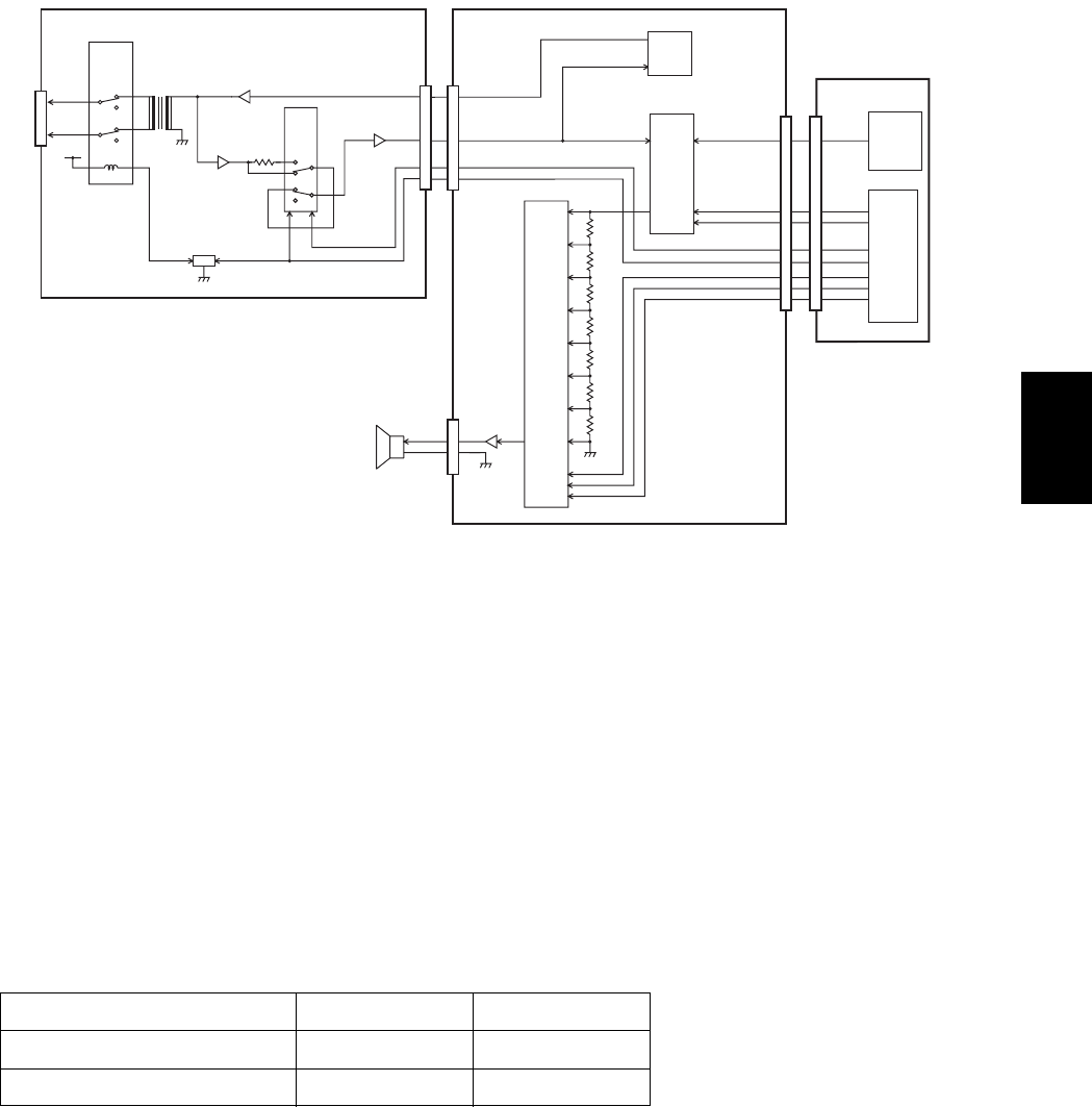
Fig. 4-13
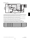
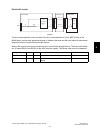
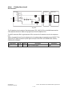
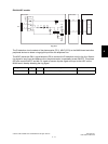
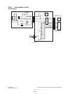
The line monitor circuit consists of the CML relay (NA/TW: RLY2, EU/AU/AS/C: RLY3), analog switch
(NA/TW: IC51, EU/AU/AS/C: IC3), analog switches (IC9, IC10) on the FAX board, ASIC (IC23) and
SoC (IC53) on the MAIN board, and other peripheral devices. It switches the telephone line path using
the analog switch and monitors the line status and ringer signal in the FAX transmission and reception
using the speaker connected to CN503 on the FAX board. It also switches the analog switch to output a
buzzer tone from the speaker.
The signal to be monitored is selected by switching the analog switch (IC9) according to TONESEL sig-
nal and RING/TONE signal which are output from the ASIC.
To monitor the line during the transmission and reception, the ASIC makes the CML1 signal become
HIGH to switch the analog switch and connect the line to the MODEM side.
For the line path switching control, refer to P. 4-4 "4.2.2 Line path switching control circuit".
The relation between the signal levels and monitoring signals is as follows.
Monitoring signal TONESEL RING/TONE
LINE Monitor LOW HIGH
Ringer/Alarm - LOW
SPVOL0
3
5
3
SPVOL1
SPVOL2
15
3
TONESEL 59
57
24
58
1
1
2
3
6
1
27
3
6
2
11
10
9
TXOUT1
RXIN1
9,10
RING/TONE 2311
CML1 27
ATT3DB1 62
SP+
SP-
Speaker
IC10
Analog
switch
IC10
IC9
Analog
switch
AG
SG
CN9
CN252
FAX board
IC2
MODEM
CN264
IC23
ASIC
IC53
SoC
CN5
MAIN board
CN5
59
57
24
58
25
23
27
62
152
150
149
151
A5
153
144
142
R273
[
R31
]
R272
[
R30
]
R271
[
R29
]
R270
[
R32
]
R268
[
R35
]
R267
[
R33
]
R266
[
R36
]
[
R37
]
25RING
[
SPKCLK
]
12
[
2
]
32
[
29
]
28,29
[
25,26
]
13
[
4
]
14
[
2
]
15
[
5
]
12
[
1
]
1
[
12
]
5
[
15
]
2
[
14
]
4
[
13
]
NCU board
CN4
IC3
Analog
switch
RLY3
CML relay
CN3
Q4
14
Lb
La
Line
4
3
13
1
2
15
11 10
T1
IC6
AG
0
1
0
1
8
12
5
9
1
4
0
1
0
1
AG
+12V
IC6
6
21
75
IC4
R11
08/08