


© 2006 - 2008 TOSHIBA TEC CORPORATION All rights reserved GD-1220/1221
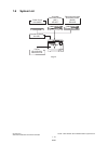
SPECIFICATIONS AND OUTLINE OF SYSTEM
1 - 3
1
3) Transmission system
Circuits to be used: Subscriber line/FAX communication network (G3)
- Calling automatic transmission (including the sequential multi-address transmission)
- Calling automatic reception (polling reception)
- Called automatic transmission (polling transmission)
- Called automatic reception
- Calling manual transmission
- Calling manual reception
- Called manual transmission
- Called manual reception
Communication mode
High-speed mode (Toshiba original procedure mode)
G3 mode
ECM (Error Correction Mode)
Circuit carrier link equalization function
Embedded
Output level
–16 dBm to –8 dBm (The setting can be changed by “1 dB”.)
Input level
–43 dBm to 0 dBm
(Level –55 dBm or lower cannot be detected)
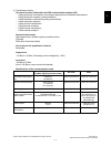
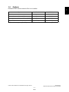
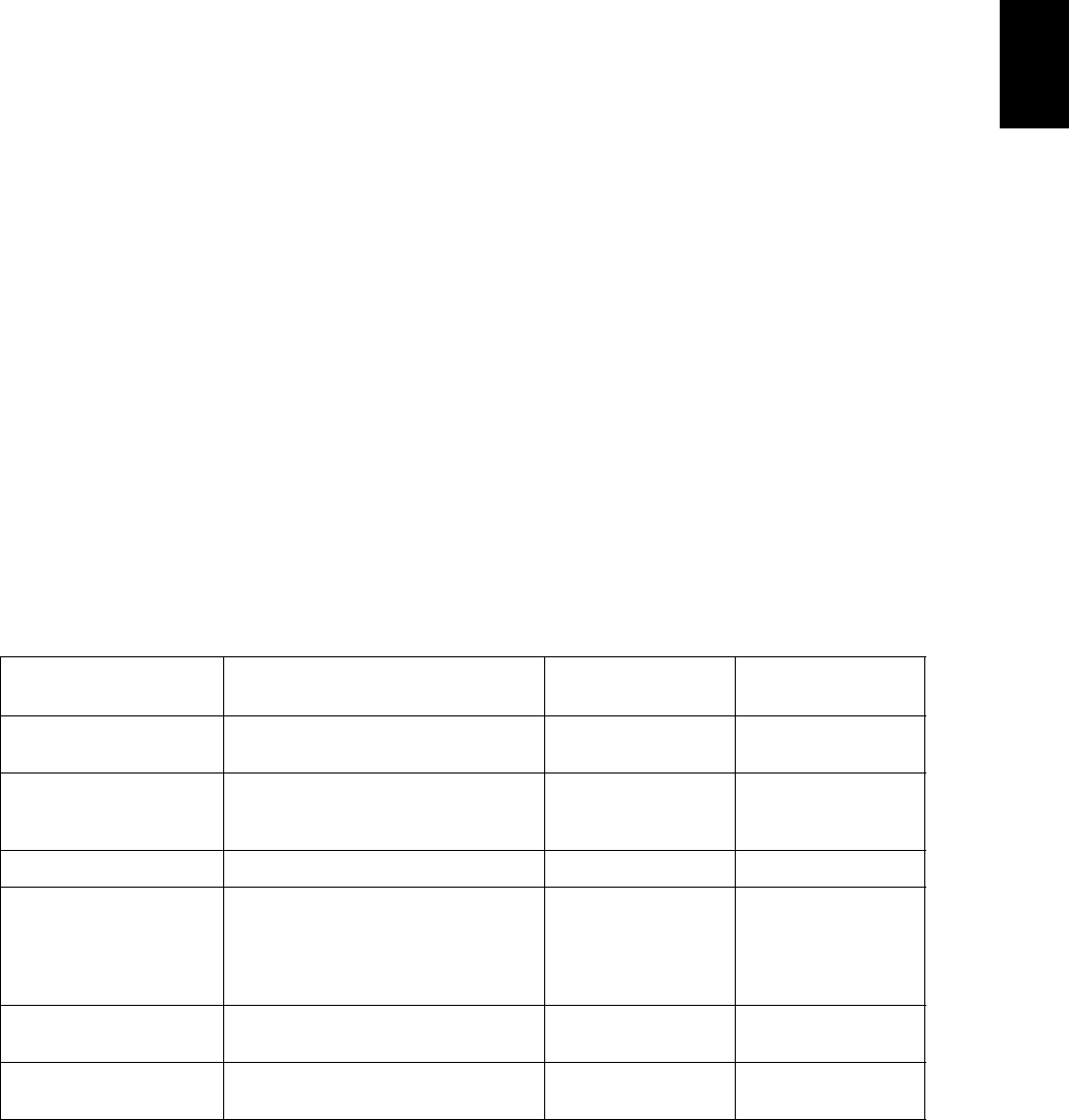
Specifications of the communication mode
High-speed mode
(Toshiba original procedure mode)
G3 mode ECM
Horizontal scanning den-
sity
8 dots/mm
16 dots/mm
Same as on the left Same as on the left
Vertical scanning density 3.85 lines/mm
7.7 lines/mm
15.4 lines/mm
Same as on the left Same as on the left
Encoding system MH/MR/MMR/JBIG MH/MR MH/MR/MMR/JBIG
Transmission speed
(image signal) and modu-
lation method
14.4 k/12 k/9600
7200/4800/2400 bps
Conformance to V.17/V.29/V.27 ter
Same as on the left 33.6 k/31.2 k/28.8 k/
26.4 k/24 k/21.6 k/
19.2 k/16.8 k/14.4 k/
12 k/9600/7200/
4800/2400 bps
Control signal 300 bps
(V.21)
Same as on the left 1200 bps (V.34)
300 bps (V.21)
Procedure to control the
transmission
Toshiba original procedure T.30 conformance Same as on the left