


GD-1220/1221 © 2006 - 2008 TOSHIBA TEC CORPORATION All rights reserved
ELECTRICAL CIRCUITS
4 - 14
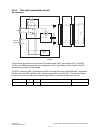
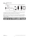
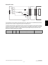
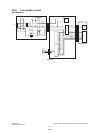
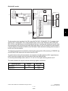
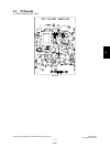
The monitoring signal selected by IC9 is input to the analog switch (IC10) to select the output sound
volume. The sound volume is selected by switching IC10 according to the SPVOL0-2 signals output
from the ASIC and selecting an input resistance for the monitoring signal.
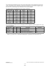
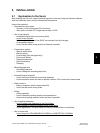
The relation between the signals and sound volume is as follows.
The monitoring signal whose volume is controlled by IC10 is amplified by the OP amplifier (IC17), then
output to the speaker.
* Values in [ ] are GD-1221 in case that the descriptions vary between GD-1220 and GD-1221.
Sound volume SPVOL2 SPVOL1 SPVOL0
Max. (7) LOW LOW LOW
(6) LOW LOW HIGH
(5) LOW HIGH LOW
(4) LOW HIGH HIGH
(3) HIGH LOW LOW
(2) HIGH LOW HIGH
Min. (1) HIGH HIGH LOW
Silent (0) HIGH HIGH HIGH
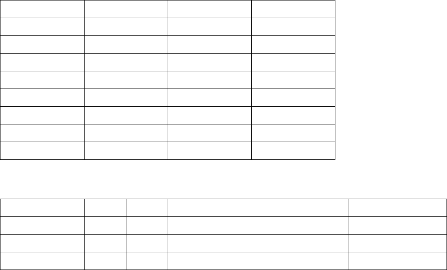
Signal Name Type Active Description Destination
TONESEL O H Line/Tone Selection Signal IC9
RING/TONE O H Ring/Tone Selection Signal IC9
SPVOL0-2 O H Speaker Volume Control Signals 0-2 IC10
08/08