9
4.3 Connection on Back Panel
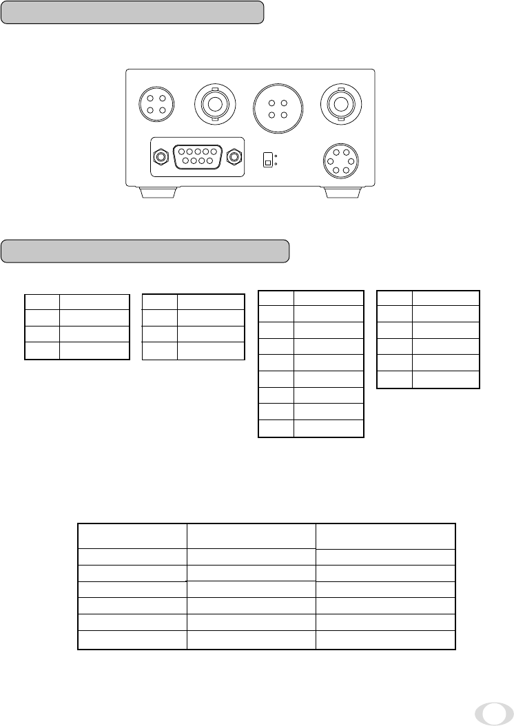
The figure below shows the back panel connection terminals of the camera control unit.
1
2
3
4
+12V
+12V
GND
GND
4.4 Connector Pin Assignments
1
2
3
4
5
6
7
8
9
NC
TXD
RXD
DSR
GND
DTR
CTS
RTS
NC
1
2
3
4
GND
GND
Y
C
1
2
3
4
5
6
NC
VIDEO
GND
+12V
GND
NC
DC IN 12V EXT
SYNC S-VIDEO
REMOTE
VIDEO
FUNC LOCK
ON
OFF
1
2
3
4
5
6789
1
2
3
4
1
2
3
4
IRIS
2
5
1
6
3
4
IRIS
REMOTE
DC IN 12V
S-VIDEO
* When using the REMOTE terminal, please consult with your dealer.
• Using the auto-iris lens
The following table shows the IRIS terminal when using the auto-iris (EE) lens.
Table 1
The IRIS connector used for the IRIS terminal: HR10A-7P-6P of HIROSE ELECTRIC
CO., LTD.
Signal
––
Video signal
GND
Power (DC)
(GND)
––
IRIS Connector
Terminal No.
1
2
3
4
5
6
Rated
0.8 ± 0.1Vp-p
+ 12V (less than 50mA)


