


14
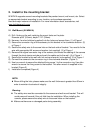
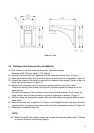
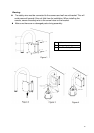
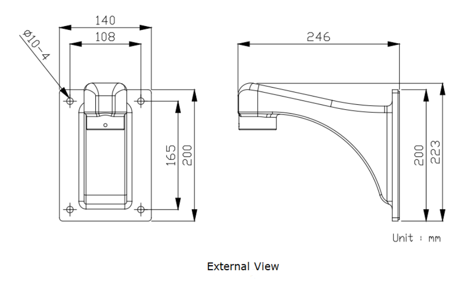
2.2 Wall Mount With Electrical Box (JK-WMB41A)
A) Drill 4 holes on the wall matching the mount holes on the plate.
Diameter φ3/8” (9.5mm), depth 1/1/2” (39mm)
B) Hammer 4 anchor bolts (not supplied) into the holes and secure them. (Figure 1)
C) Secure the electrical box to the wall with hex nuts and wrench (not supplied). (Figure 2)
D) Loosen the screws of the lid with a supplied torx wrench in the bracket. (Note: Leave in a
lower right screw shown in Figure 2.)
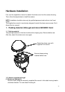
E) Remove the connector ring of the camera, and secure this ring to the U tube.
Thread the cabling of the camera through the U tube and push the cables out to the
electrical box.
Connect the camera to the connector ring in the clockwise direction.Then secure the
fixing screws 1and 2 to the connector ring with a supplied torx wrench. (Figure 3)
F) After all cables are connected; please make sure the cables are properly fitted to avoid
water leaks.
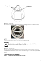
G) Secure the safety wire to position C in Figure 1 with supplied screw. And return the lid to
original position and secure the screws of the lid with a supplied torx wrench. (Figure 4)
H) Installation completed (Figure 5).
NOTE:
When drilling the hole, please make sure the wall thickness is greater than 2” (50mm)
in order to maintain its structural integrity.