


17
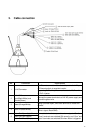
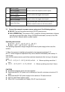
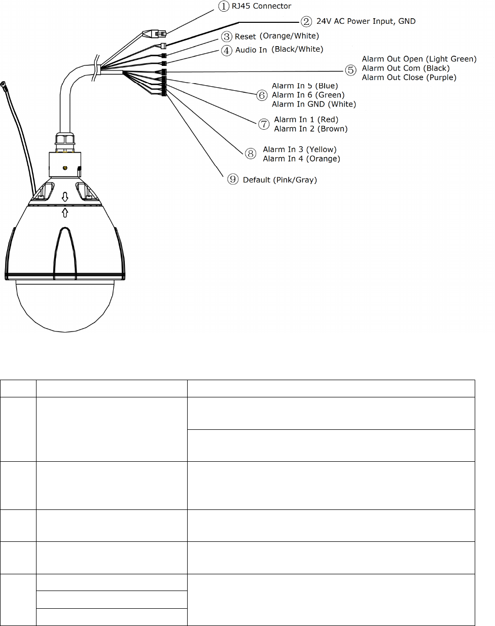
3. Cable connection
No. Connector Descriptions
1 RJ-45 Connector
For Ethernet connection. Connects this port to the LAN port
of Ethernet switch via supplied coupler.
Supporting PoE+, this port can connect to the PoE+ switch
or PoE+ injector.
2
24V AC Power
Input(Black/White) and
Ground(Green)
Connect the power terminals to a 24V AC power supply
and
ground the green wire.
3 Reset (Orange/White)
Using a pointed object, short both terminals to restart the
camera.
4 Audio In (Black/White)
Connect to an external microphone to this terminal.
(White: signal, Black:GND)
5
Alarm Out Open (Light Green)
Connect to device that responds to alarm signals. “Com”
and
“Close” terminals are switched ON normally, and “Com” and
“Open” terminals are switched ON when Alarm is triggered.
Alarm Out Com (Black)
Alarm Out Close (Purple)