


18
6
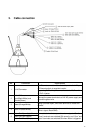
Alarm In 5 (Blue)
Connect to device that responds to alarm signals. Alarm In 6 (Green)
Alarm In GND (White)
7
Alarm In 1 (Red)
Connect to device that triggers alarm signals.
Alarm in 2 (Brown)
8
Alarm In 3 (Yellow)
Connect to device that triggers alarm signals.
Alarm in 4 (Orange)
9 Default (Pink/Gray)
Using a pointed object, short both terminals for about 5
seconds to restart the camera to the factory default.
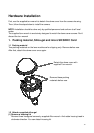
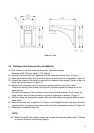
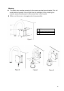
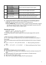
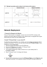
3.1 Connect the camera to a power source, using one of the following options:
24V AC: Connect the power terminals to 24V AC power source.
PoE+ (IEEE802.3at): The camera is PoE+ compliant, allowing transmission of power
and data via single LAN cable. Using a CAT5e Ethernet cable, connect to the LAN
port of a PoE+ network switch or power injector.
Operating environment:
24V AC : –30 °C ~ +50 °C {–22 °F ~ 122 °F}*1
PoE+ : -10°C ~ +50 °C {14 °F ~122 °F} *1
The operating temperature range changes with kinds of power supply which uses this
camera.
*1 When the camera is installed and operated in low temperatures below 0 °C
{32 °F}, normal images and operations may not be obtained immediately after startup. In
such a case,
wait until the camera warms up as follows and start adjustment after turning on the power
again.
-10 °C ~ 0 °C {14 °F ~ 32 °F}, 24V AC or PoE+ Warms up taking more than 1
hour.
-30 °C ~ -10 °C {-22 °F ~ 14 °F}, 24V AC Warms up taking more than 3 hours.
CAUTION
All cables and power source are user-supplied.
Recommended 24V AC power cord is twisted pair line with a minimum wire size of 18
AWG.
Recommended 24V AC power supply for this camera is 75 watts minimum.
Use UL Listed Class 2 power supply.
When PoE+ is connected, don't supply 24V AC from the terminal.