


4.11 Cover assembly 4 Replacement Procedures
QOSMIO G30 Maintenance Manual (960-546) [CONFIDENTIAL] 4-31
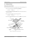
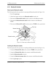
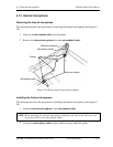
Installing the cover assembly
The following describes the procedure for installing the cover assembly (See Figure 4-15 to
4-17).
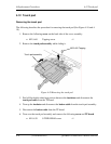
1. Install the cover assembly to the base assembly in place.
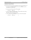
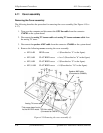
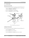
2. Connect the microphone cable to the connector CN6050 on the system board.
3. Connect the switch board cable to the connector CN9650 on the system board.
4. Connect the fingerprint sensor cable to the connector CN9530 on the system board.
5. Connect the volume cable to the connector CN3330 on the system board.
6. Connect the touch pad cable to the connector CN3201 on the system board.
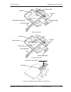
7. Connect the FL inverter to the connector CN5816 on the system board.
8. Connect the LCD cable from the connector CN5000 on the system board.
9. Install the LCD connector cover in place.
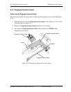
10. Secure the cover assembly with the following screw.
• M2.5×8B FLAT BIND screw ×1
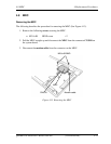
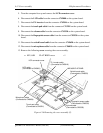
11. Turn over the computer.
12. Connect the GPU fan cable to the connector CN8781 on the system board.
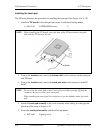
13. Connect the analog TV turner cable and analog TV turner antenna cable to the
analog TV tuner.
14. Connect the speaker AMP cable from the connector CN6480 on the system board.
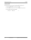
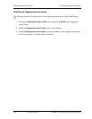
15. Secure the cover assembly with the following screws
• M2.0×4B BIND screw ×1 (Described as "4" in the figure 4-15)
• M2.5×6B FLAT BIND screw ×4 or ×3 (Described as "6" in the
figure 4-15)
• M2.5×8B FLAT BIND screw ×3 (Described as "8" in the figure 4-15)
• M2.5×16B FLAT BIND screw ×14 (Described as "16" in the
figure 4-15)